Home /
Expert Answers /
Electrical Engineering /
consider-the-biased-parallel-clipper-circuit-shown-below-1-consider-the-biased-parallel-clipper-pa602
(Solved): Consider the biased parallel clipper circuit shown below. 1. Consider the biased parallel clipper ...
Consider the biased parallel clipper circuit shown below.
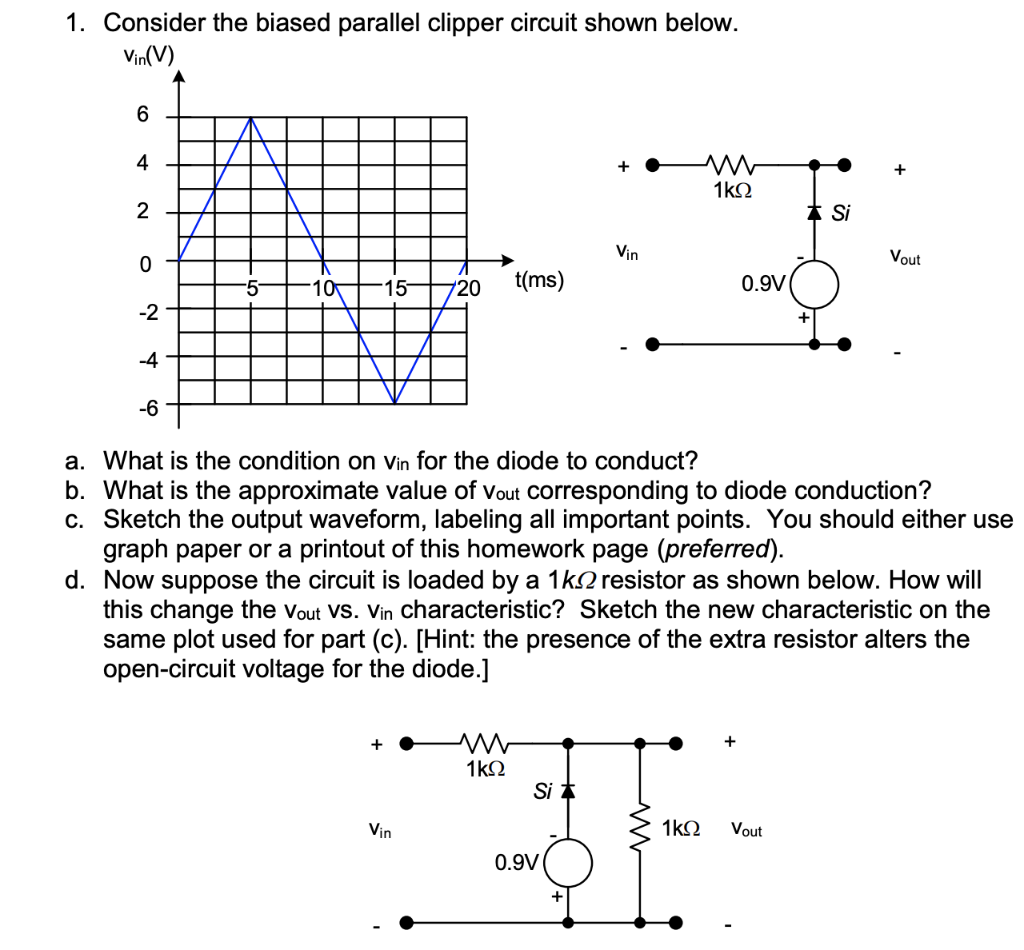
1. Consider the biased parallel clipper circuit shown below. a. What is the condition on vin for the diode to conduct? b. What is the approximate value of Vout corresponding to diode conduction? c. Sketch the output waveform, labeling all important points. You should either use graph paper or a printout of this homework page (preferred). d. Now suppose the circuit is loaded by a resistor as shown below. How will this change the vout vs. vin characteristic? Sketch the new characteristic on the same plot used for part (c). [Hint: the presence of the extra resistor alters the open-circuit voltage for the diode.]
Expert Answer
The positive terminal of the diode is set to -0.9V. The voltage of the silicon diode for conduction is 0.7V. So wh