Home /
Expert Answers /
Electrical Engineering /
figure-2-b-stage-2-with-locked-rotor-and-50-volts-applied-to-the-stator-the-current-was-18-ampere-pa874
(Solved): FIGURE 2 b) Stage 2: With locked rotor and 50 volts applied to the stator, the current was 18 ampere ...
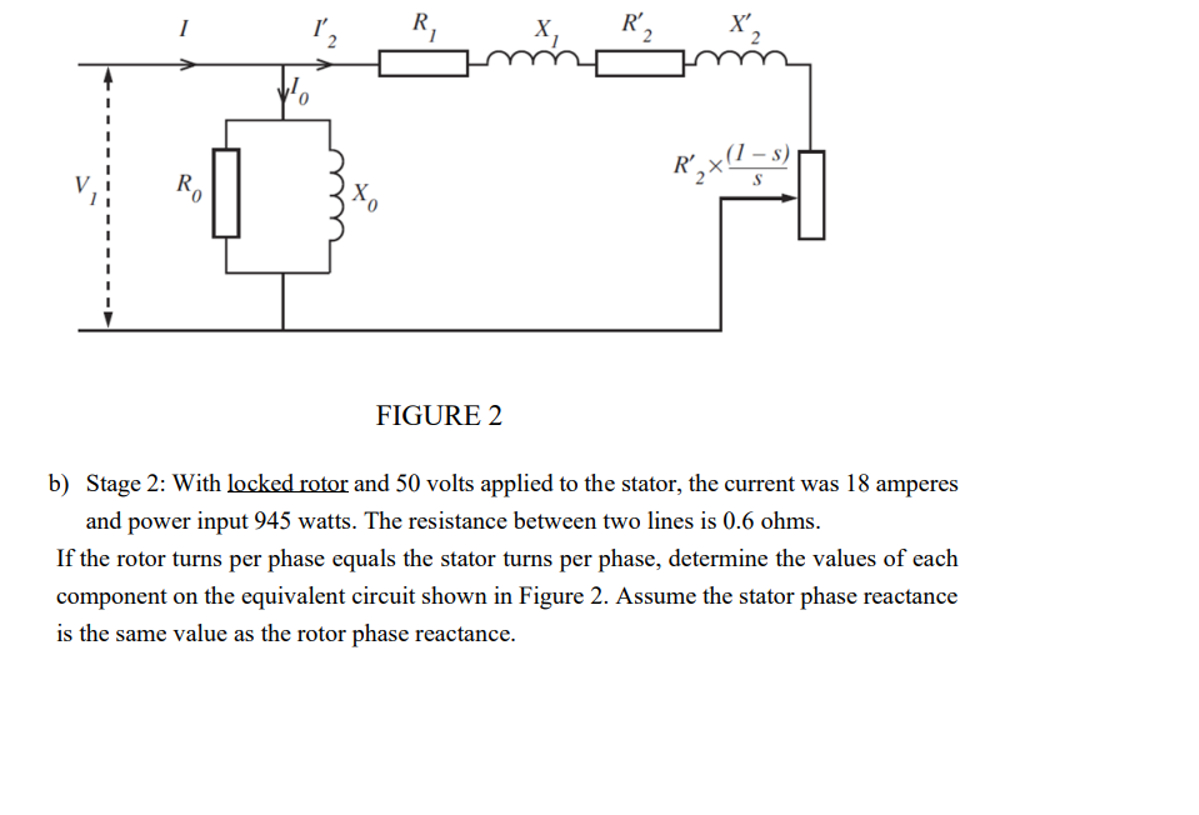
FIGURE 2 b) Stage 2: With locked rotor and 50 volts applied to the stator, the current was 18 amperes and power input 945 watts. The resistance between two lines is 0.6 ohms. If the rotor turns per phase equals the stator turns per phase, determine the values of each component on the equivalent circuit shown in Figure 2. Assume the stator phase reactance is the same value as the rotor phase reactance. **Please show all working out values of each component thanks :)**