(Solved): 1. MODELING A SERIES RLC CIRCUIT Given an RLC circuit in Figure 1.1, the current of the circuit is r ...
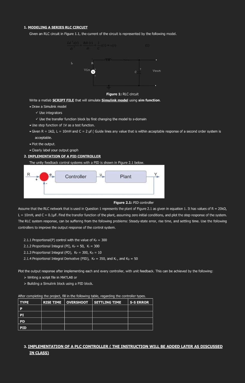
1. MODELING A SERIES RLC CIRCUIT Given an RLC circuit in Figure 1.1, the current of the circuit is represented by the following model. Write a mattab SCRIPT FILE that will simulate Simulink model using sim function. - Draw a Simulink model \( \checkmark \) Use integrators \( \checkmark \) Use the transfer function block by first changing the model to s-domain - Use step function of 1 V as a test function. - Given \( R=1 \mathrm{k} \Omega, \mathrm{L}=10 \mathrm{mH} \) and \( \mathrm{C}=2 \mu \mathrm{f} \) ( Guide lines any value that is within acceptable response of a second order system is acceptable. - Plot the output. - Clearly label your output graph 2. IMPLEMENTATION OF A PID CONTROLLER The unity feedback control systems with a PID is shown in Figure 2.1 below. Figure 2.1: PID controller Assume that the RLC network that is used in Question 1 represents the plant of Figure 2.1 as given in equation 1 . It has values of \( \mathrm{R}=20 \mathrm{k} \Omega \), \( \mathrm{L}=10 \mathrm{mH} \), and \( \mathrm{C}=0.1 \mu \mathrm{~F} \). Find the transfer function of the plant, assuming zero initial conditions, and plot the step response of the system. The RLC system response, can be suffering from the following problems: Steady-state error, rise time, and settling time. Use the following controllers to improve the output response of the control system. 2.1.1 Proportional( P ) control with the value of \( \mathrm{K}_{9}=300 \) 2.1.2 Proportional Integral (PI), \( K_{p}=50, K_{i}=300 \) 2.1.3 Proportional Integral (PD), \( \mathrm{K}_{\mathrm{p}}=300, \mathrm{~K}_{\mathrm{D}}=10 \) 2.1.4 Proportional Integral Derivative (PID), \( K_{P}=350 \), and \( K_{1} \), and \( K_{D}=50 \) Plot the output response after implementing each and every controller, with unit feedback. This can be achieved by the following: - Writing a script file in MATLAB or > Building a Simulink block using a PID block. After completing the project, fill in the following table, regarding the controller types. 3. TMPLEMENTATION OF A PLC CONTROLLER (THE TNSTRUCITON WTLL BE ADDED LATER AS DISCUSSED INCLASS)