Home /
Expert Answers /
Computer Science /
2-draw-the-logic-diagram-of-a-3-bit-parallel-in-parallel-out-register-with-mode-selection-inputs-pa180
(Solved): 2. Draw the logic diagram of a 3-bit parallel in parallel out register with mode selection inputs ...
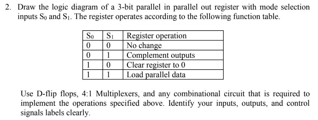
2. Draw the logic diagram of a 3-bit parallel in parallel out register with mode selection inputs So and S?. The register operates according to the following function table. So S? Register operation 0 0 No change 0 1 Complement outputs 1 0 Clear register to 0 1 1 Load parallel data Use D-flip flops, 4:1 Multiplexers, and any combinational circuit that is required to implement the operations specified above. Identify your inputs, outputs, and control signals labels clearly.