Home /
Expert Answers /
Electrical Engineering /
2-the-circuit-shown-in-figure-b2-uses-a-silicon-diode-a-calculate-the-peak-currents-i-il-and-pa171
(Solved): 2. The circuit shown in Figure B2 uses a silicon diode. (a) Calculate the peak currents I,IL and ...
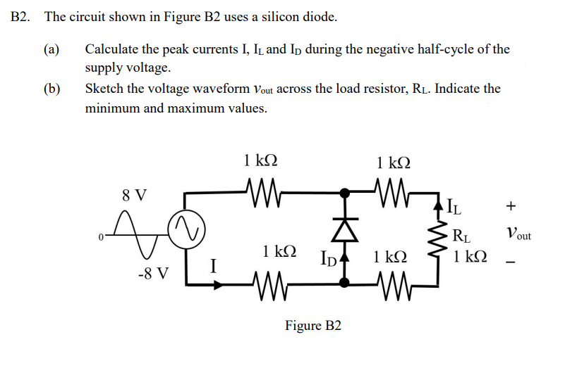
2. The circuit shown in Figure B2 uses a silicon diode. (a) Calculate the peak currents and during the negative half-cycle of the supply voltage. (b) Sketch the voltage waveform across the load resistor, . Indicate the minimum and maximum values.