Home /
Expert Answers /
Electrical Engineering /
2-the-input-signal-in-figure-1-a-is-applied-to-the-comparator-in-figure-1-b-draw-the-output-show-pa192
(Solved): 2. The input signal in Figure 1(a) is applied to the comparator in Figure 1(b).Draw the output show ...
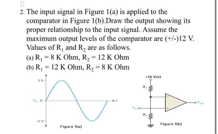
2. The input signal in Figure 1(a) is applied to the comparator in Figure 1(b).Draw the output showing its proper relationship to the input signal. Assume the maximum output levels of the comparator are \( (+/-) 12 \mathrm{~V} \). Values of \( \mathrm{R}_{1} \) and \( \mathrm{R}_{2} \) are as follows. (a) \( \mathrm{R}_{1}=8 \mathrm{~K} \mathrm{Ohm}, \mathrm{R}_{2}=12 \mathrm{~K} \mathrm{Ohm} \) (b) \( \mathrm{R}_{1}=12 \mathrm{~K} \mathrm{Ohm}, \mathrm{R}_{2}=8 \mathrm{~K} \mathrm{Ohm} \)