Home /
Expert Answers /
Electrical Engineering /
28-29-q-2-30-consider-the-circuit-shown-in-figure-q-2-using-both-the-simplified-approach-and-also-r-pa314
(Solved): 28 29 Q.2 30 Consider the circuit shown in Figure Q.2. Using both the simplified approach and also r ...
28 29 Q.2 30 Consider the circuit shown in Figure Q.2. Using both the simplified approach and also replacing 31 the base bias circuit with Thevenin equivalent circuit find the output voltage VCE. 32 33 34 35 36 37 38 834 39 40 41 42 43 44 45 46 T: R1 = R2 = RC 2 = RE 2 = 11-13 hFE = 64 30 850 1350 90 Question k Ohms k Ohms Ohms Ohms R1 R2 RC 2 RE 2 [25 marks] 12 V
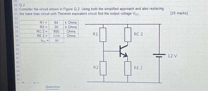
Consider the circuit shown in Figure Q.2. Using both the simplified approach and also replacing the base bias circuit with Thevenin equivalent circuit find the output voltage .
Expert Answer
The BJT works in active region when & the BJT works in saturation region when Applying theveni...