Home /
Expert Answers /
Electrical Engineering /
3-for-the-circuit-shown-in-figure-b3-a-calculate-the-peak-voltage-of-the-secondary-coil-b-ca-pa953
(Solved): 3. For the circuit shown in Figure B3, (a) calculate the peak voltage of the secondary coil. (b) ca ...
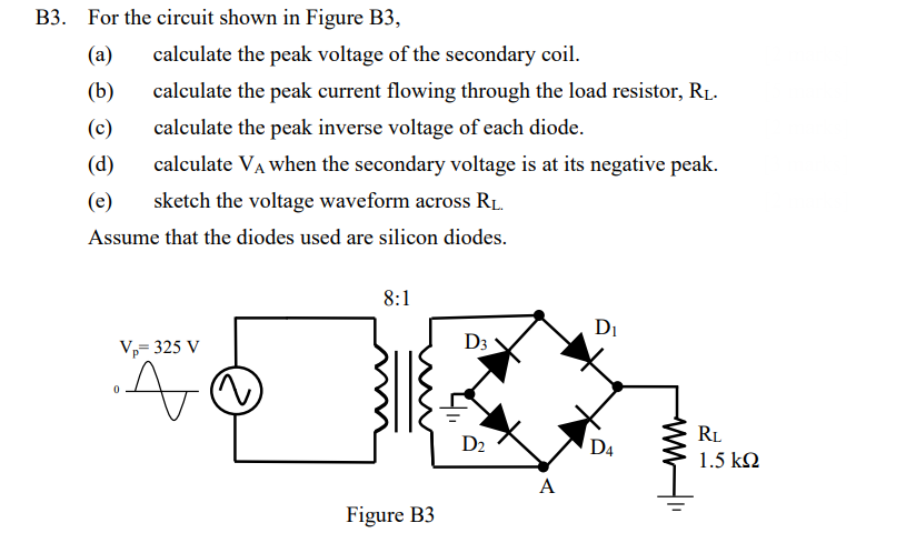
3. For the circuit shown in Figure B3, (a) calculate the peak voltage of the secondary coil. (b) calculate the peak current flowing through the load resistor, . (c) calculate the peak inverse voltage of each diode. (d) calculate when the secondary voltage is at its negative peak. (e) sketch the voltage waveform across . Assume that the diodes used are silicon diodes.