Home /
Expert Answers /
Civil Engineering /
3-the-member-shown-in-figure-3-is-part-of-a-braced-frame-the-axial-force-and-moments-at-both-ends-pa233
(Solved): 3. The member shown in Figure 3 is part of a braced frame. The axial force and moments at both ends ...
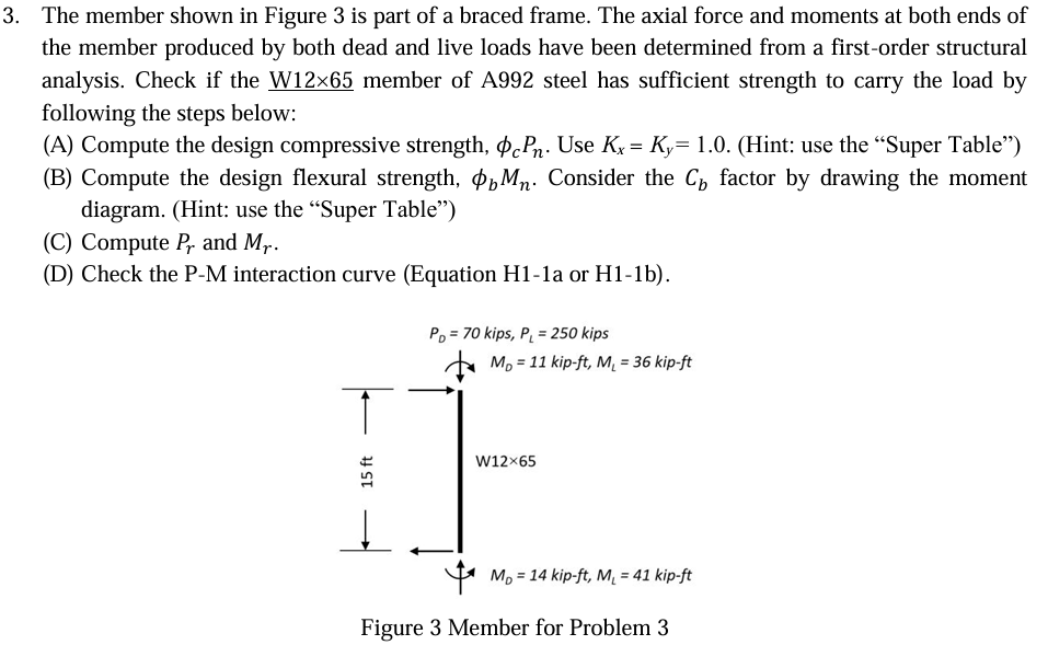
3. The member shown in Figure 3 is part of a braced frame. The axial force and moments at both ends of the member produced by both dead and live loads have been determined from a first-order structural analysis. Check if the W12\times 65  member of A992 steel has sufficient strength to carry the load by following the steps below:
(A) Compute the design compressive strength, \phi _(c)P_(n). Use K_(x)=K_(y)=1.0. (Hint: use the "Super Table")
(B) Compute the design flexural strength, \phi _(b)M_(n). Consider the C_(b) factor by drawing the moment diagram. (Hint: use the "Super Table")
(C) Compute P_(r) and M_(r).
(D) Check the P-M interaction curve (Equation H1-1a or H1-1b)