Home /
Expert Answers /
Electrical Engineering /
8-9-using-figure-8-6-and-figure-8-7-as-a-guide-draw-the-full-gate-level-schematic-fo-pa903
(Solved): 8.9. Using Figure \( 8.6 \) and Figure \( 8.7 \) as a guide, draw the full gate-level schematic fo ...

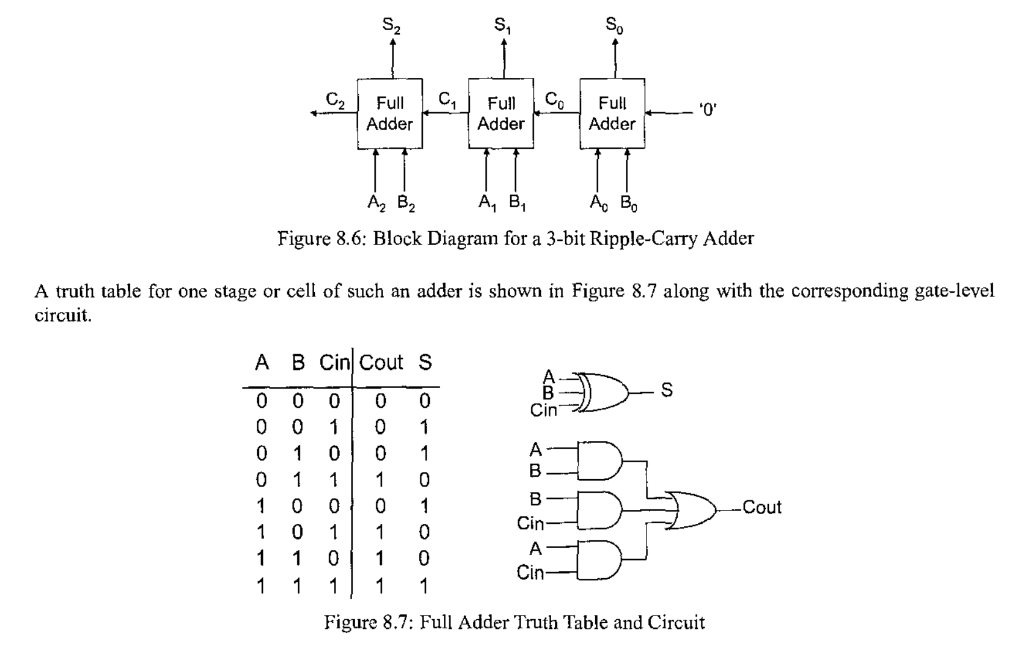
8.9. Using Figure \( 8.6 \) and Figure \( 8.7 \) as a guide, draw the full gate-level schematic for a 3-bit adder. Can you write how many gates are required, in general, for an \( n \)-bit ripple carry adder?
Figure 8.6: Block Diagram for a 3-bit Ripple-Carry Adder A truth table for one stage or cell of such an adder is shown in Figure \( 8.7 \) along with the corresponding gate-level circuit. Figure 8.7: Full Adder Truth Table and Circuit
Expert Answer
To implement one full adder 5 gates (one EXOR gate 3 AND gate