Home /
Expert Answers /
Civil Engineering /
a-3b-4c-5d-6-the-drilled-shaft-foundation-shown-in-figure-3-is-to-be-designed-to-carry-a-downward-al-pa507
(Solved): a=3b=4c=5d=6 The drilled shaft foundation shown in Figure 3 is to be designed to carry a downward al ...
a=3
b=4
c=5
d=6
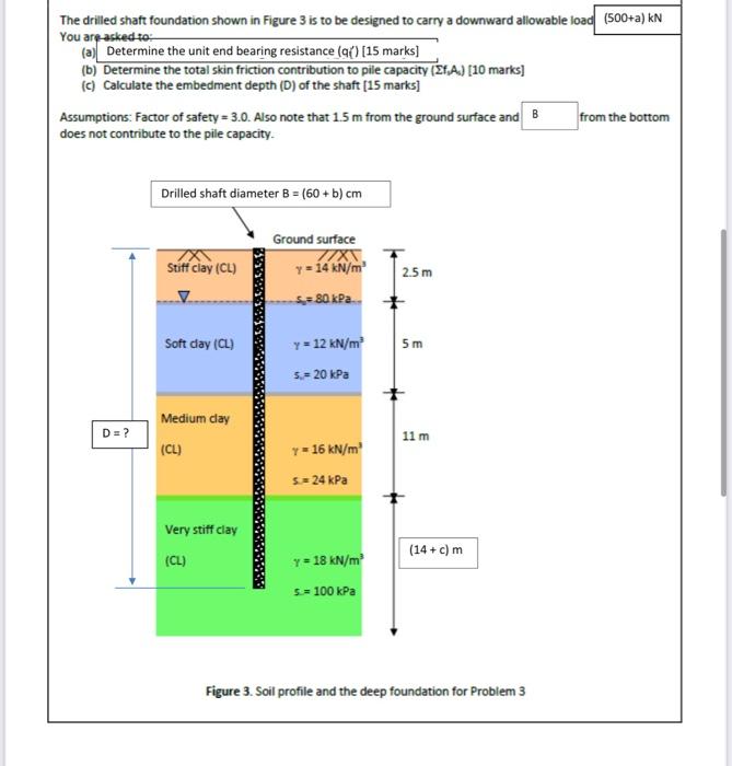
The drilled shaft foundation shown in Figure 3 is to be designed to carry a downward allowable load (500+a) kN You are asked to: (a) Determine the unit end bearing resistance (q() [15 marks] (b) Determine the total skin friction contribution to pile capacity (Ef.A.) [10 marks] (c) Calculate the embedment depth (D) of the shaft [15 marks] from the bottom Assumptions: Factor of safety = 3.0. Also note that 1.5 m from the ground surface and B does not contribute to the pile capacity. Drilled shaft diameter B = (60 + b) cm Ground surface 77XX 7X\ Stiff clay (CL) y = 14 kN/m² 2.5m S80 kPa.. Soft clay (CL) y = 12 kN/m² 5m 5,= 20 kPa Medium clay 11 m (CL) Y = 16 kN/m² S.= 24 kPa Very stiff clay (14+ c) m (CL) Y = 18 kN/m² 5.= 100 kPa Figure 3. Soil profile and the deep foundation for Problem 3 D = ?
Expert Answer
Given, Allowable loads = (500 + a) KN Factor of safety = 3 1. Allowable loads = 500 + a = 500 + 3 = 503 KN Design load = factor of safety * allowable load = 3 *