(Solved): A linear regulator is a widely used electronc device that maintains a constant output voltage regard ...
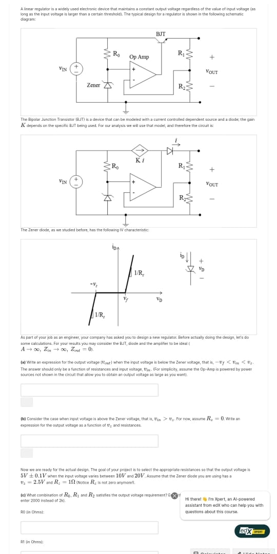
A linear regulator is a widely used electronc device that maintains a constant output voltage regardless of the value of input voltage (as long as the inpua valtage is larger than a certain threshold). The typical design for a reguiator is shown in the following schermatic diagram: The Alipolar Junction Transistor (BJT) is a device that can be modeled with a current contraled dependent source and a dode; the gain
Kdepends on the specific B.J being used. For our analysis we will use that model, and therefore the circuit is: The Zener dode, as we studied before, has the following IV characteristic: As part of yaur joh as an engineer, your company has asked you to design a new regulator. Before actualry doing the design, let's do some calculations. For your results you mary consider the BUT, diode and the amplifier to be ideal (
A->\infty ,Z_(in )->\infty ,Z_(ouf )=0. (a) Write an expression for the output voltage when the input voltage is below the Zener voltage, that
v_(in )◻v_(in)>v_(z)R_(2)=0v_(z)◻5V+-0.1V10V20Vv_(2)=2.5VR_(2)=1\Omega R_(2)R_(0),R_(1)R_(2)x2klia,-v_(f) The answer should anly be a functian of resistances and input valtage, v_(in ). For simplicity, assume the Op-Amp is powered by pawet sources not shown in the circut that allow you to obtain an output voitage os large an you want!
◻
(b) Consider the case when irput voRage is above the Zener veltage, that is, v_(in)>v_(z). For now, assume R_(2)=0. Write an expressian for the output woltage as a function of v_(z) and resistances
◻
Now we are ready for the actual design. The goal of your project is to select the appropriate resistances so that the output voltage is 5V+-0.1V when the hput woltage varies between 10V and 20V. Assume that the Zener diode you are using tras a v_(2)=2.5V and R_(2)=1\Omega  (Notice R_(2) is not zero armmorell.
)
(
(o) What combination of R_(0),R_(1) and R_(2) satisfies the output valtage requirement? E x ) enter 2000 instead of 2kl.
90 lin Otms