Home /
Expert Answers /
Electrical Engineering /
a-speed-control-system-for-a-magnetic-tape-drive-is-shown-in-the-figure-below-where-j-0-1kgm2-pa648
(Solved): A speed control system for a magnetic tape-drive is shown in the figure below, where J=0.1kgm2 ...
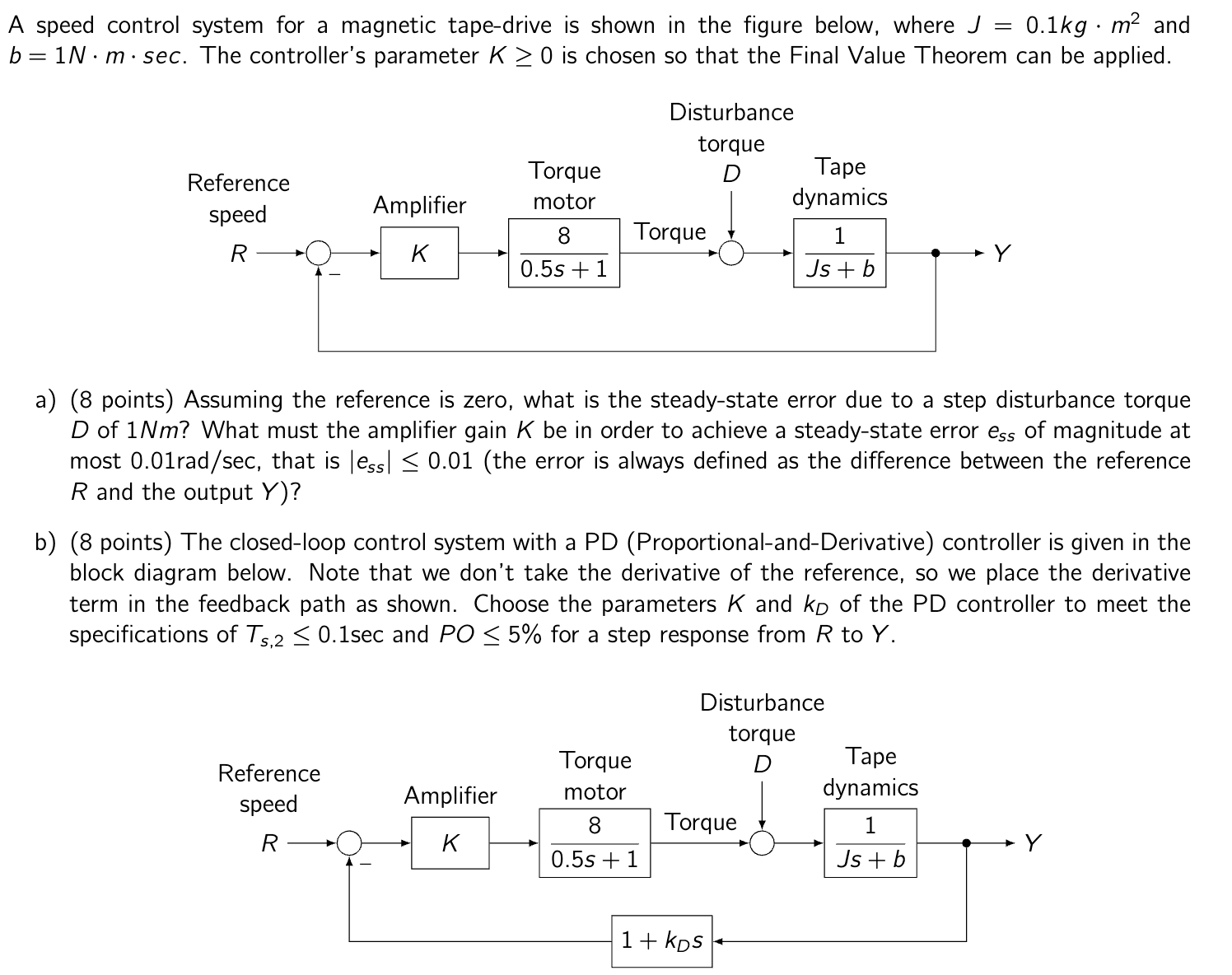
A speed control system for a magnetic tape-drive is shown in the figure below, where and . The controller's parameter is chosen so that the Final Value Theorem can be applied. a) (8 points) Assuming the reference is zero, what is the steady-state error due to a step disturbance torque of ? What must the amplifier gain be in order to achieve a steady-state error of magnitude at most , that is (the error is always defined as the difference between the reference and the output ? b) (8 points) The closed-loop control system with a PD (Proportional-and-Derivative) controller is given in the block diagram below. Note that we don't take the derivative of the reference, so we place the derivative term in the feedback path as shown. Choose the parameters and of the PD controller to meet the specifications of and for a step response from to .