Home /
Expert Answers /
Electrical Engineering /
b-a-signal-conditioning-circuit-to-be-used-in-a-measurement-system-is-shown-in-figure-4-1-the-o-pa300
(Solved): (b) A signal conditioning circuit to be used in a measurement system is shown in Figure 4.1. The o ...
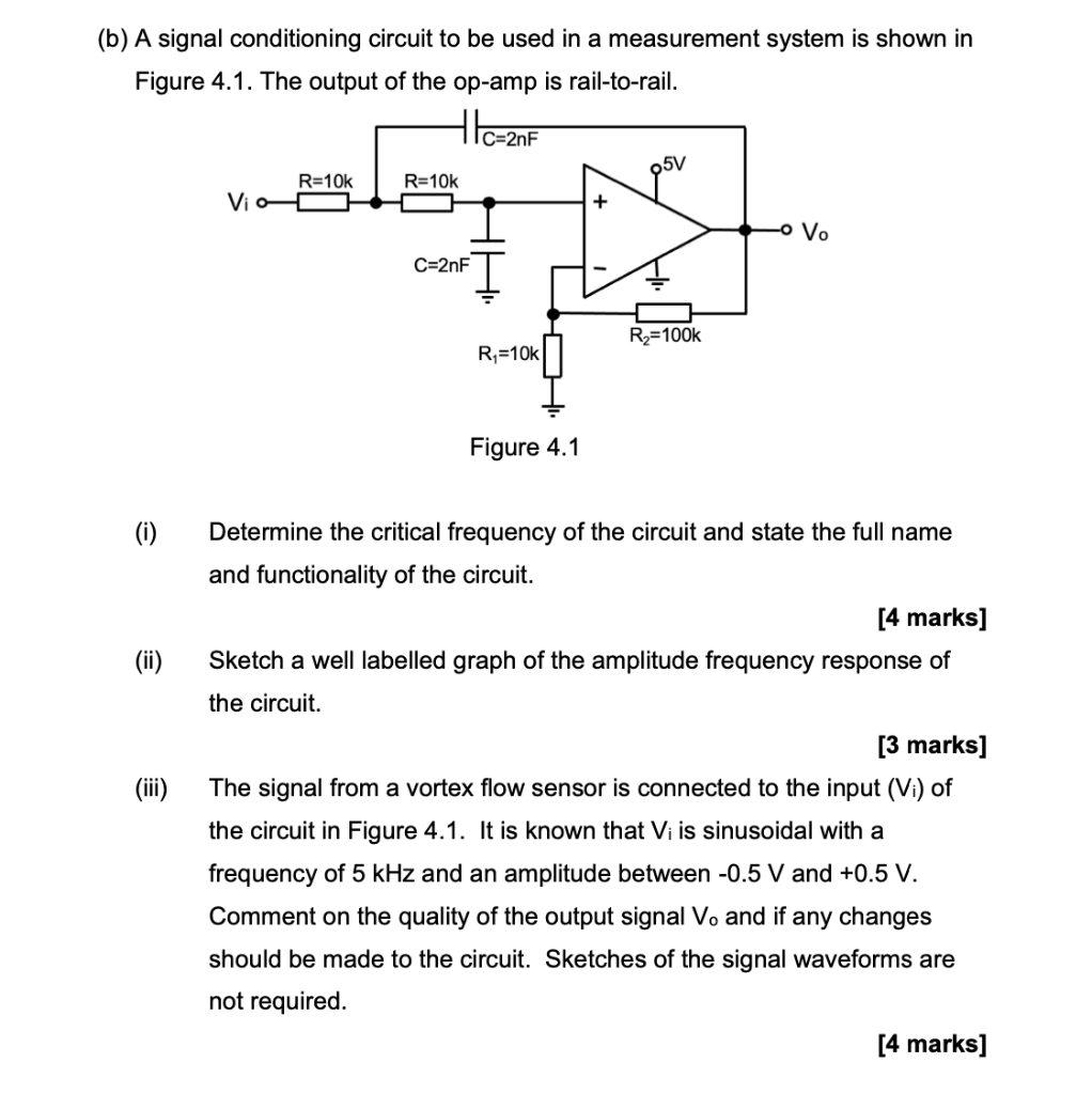
(b) A signal conditioning circuit to be used in a measurement system is shown in Figure 4.1. The output of the op-amp is rail-to-rail. C=2nF 05V R=10k R=10k Vio 88 + -o Vo C=2nF R?=100k R?=10k Figure 4.1 (i) Determine the critical frequency of the circuit and state the full name and functionality of the circuit. [4 marks] (ii) Sketch a well labelled graph of the amplitude frequency response of the circuit. [3 marks] (iii) The signal from a vortex flow sensor is connected to the input (Vi) of the circuit in Figure 4.1. It is known that Vi is sinusoidal with a frequency of 5 kHz and an amplitude between -0.5 V and +0.5 V. Comment on the quality of the output signal Vo and if any changes should be made to the circuit. Sketches of the signal waveforms are not required. [4 marks]