Home /
Expert Answers /
Electrical Engineering /
circuit-circuit-the-objective-of-this-experiment-is-to-simplify-the-circuit-in-figure-3-into-its-the-pa914
(Solved): circuit Circuit The objective of this experiment is to simplify the circuit in Figure 3 into its The ...
circuit
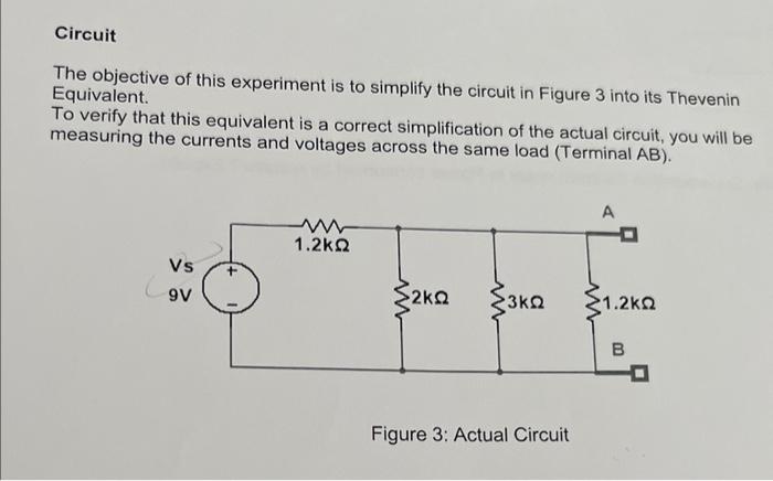
Circuit The objective of this experiment is to simplify the circuit in Figure 3 into its Thevenin Equivalent. To verify that this equivalent is a correct simplification of the actual circuit, you will be measuring the currents and voltages across the same load (Terminal \( A B \) ). Figure 3: Actual Circuit
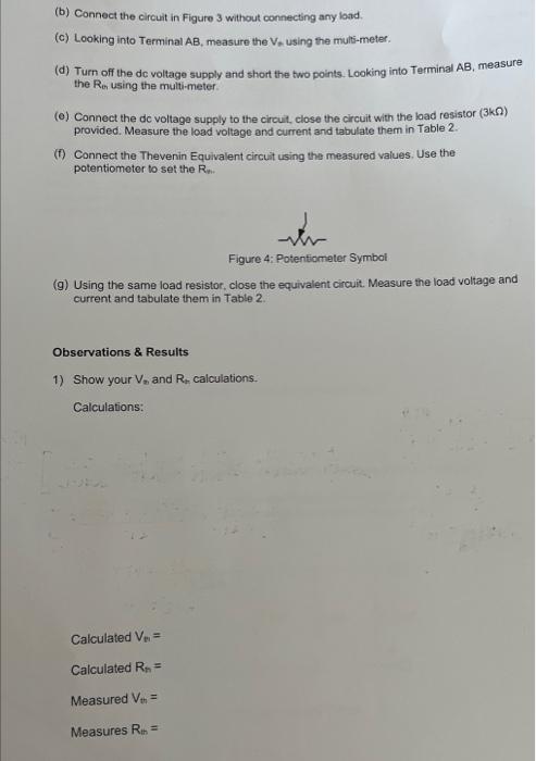
(b) Connect the circuit in Figure 3 without connecting any load. (c) Looking into Terminal \( A B \), measure the \( V_{\text {o }} \) using the multi-meter. (d) Turn off the dc voltage supply and short the two points. Looking into Terminal AB, measure the Rer using the multi-meter. provided. Measure the load voltage and current and tabulate them in Table 2. (f) Connect the Thevenin Equivalent circuit using the measured values. Use the potentiometer to set the \( R_{n \text {. }} \) (g) Using the same load resistor, close the equivalent circuit. Measure the load voltage and current and tabulate them in Table 2. Observations \& Results 1) Show your \( V_{n} \) and \( R_{t} \) calculations. Calculations:
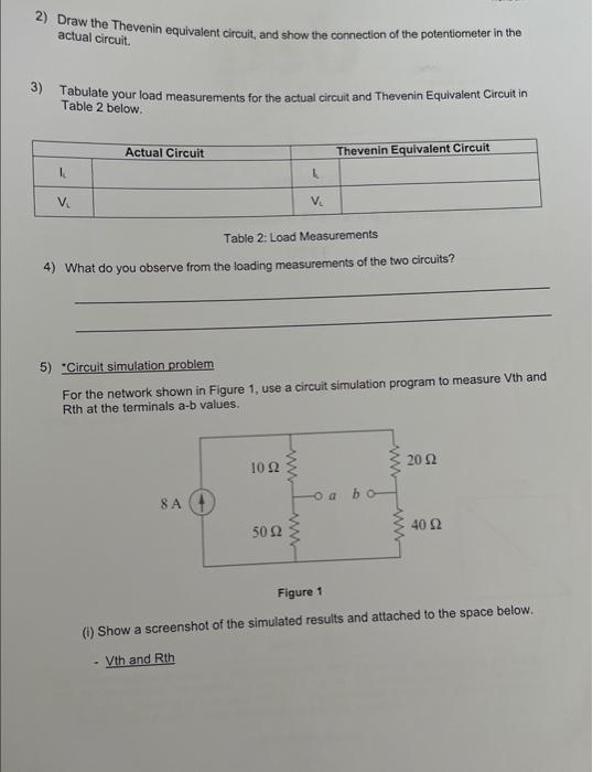
2) Draw the Thevenin equivalent circuit, and show the connection of the potentiometer in the actual circuit. 3) Tabulate your load measurements for the actual circuit and Thevenin Equivalent Circuit in Table 2 below. Table 2: Load Measurements 4) What do you observe from the loading measurements of the two circuits? 5) "Circuit simulation problem For the network shown in Figure 1, use a circuit simulation program to measure Vth and Rth at the terminals a-b values. Figure 1 (i) Show a screenshot of the simulated results and attached to the space below. - Vth and Rth