Home /
Expert Answers /
Electrical Engineering /
consider-the-block-diagram-outlined-in-figure-q4-block-diagram-outlining-all-the-signals-and-trans-pa726
(Solved): Consider the block diagram outlined in figure Q4 block diagram outlining all the signals and trans ...
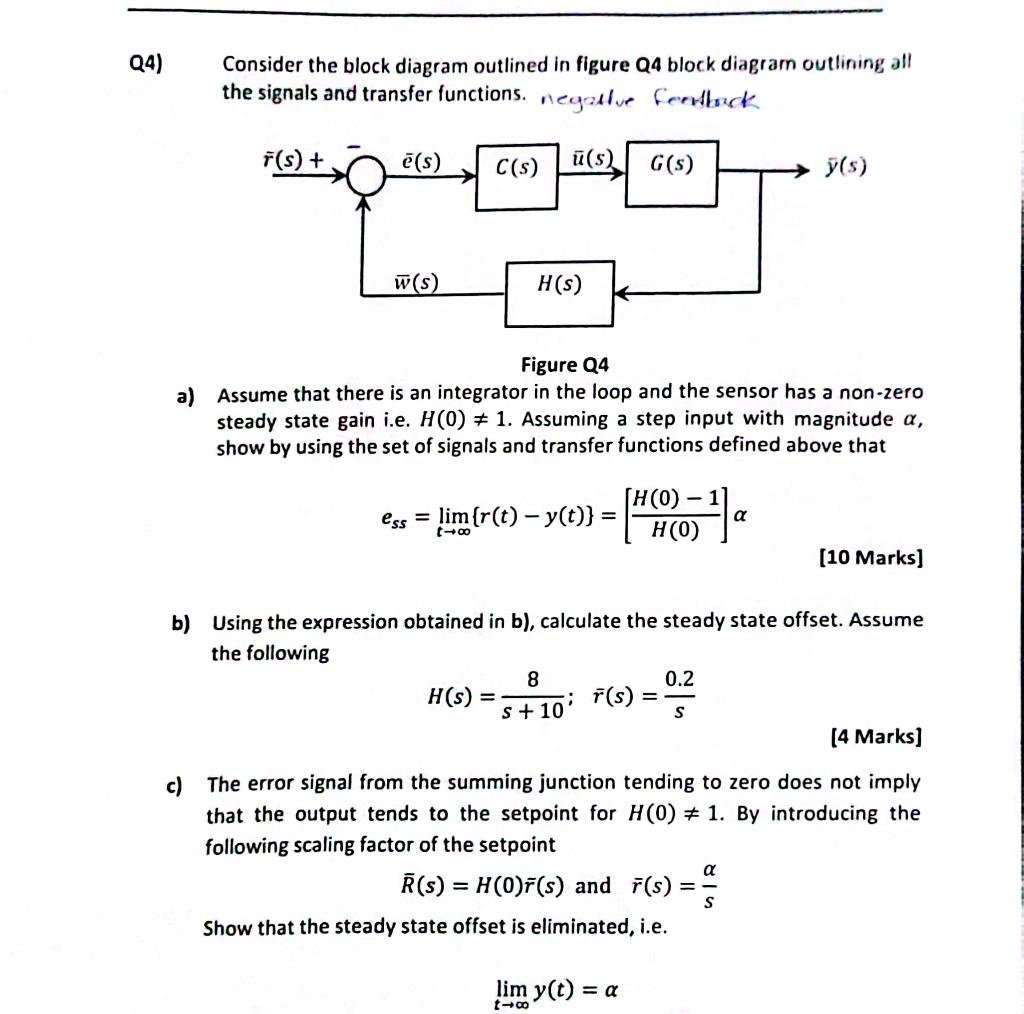
Consider the block diagram outlined in figure Q4 block diagram outlining all the signals and transfer functions. negalive ferdback Figure Q4 a) Assume that there is an integrator in the loop and the sensor has a non-zero steady state gain i.e. \( H(0) \neq 1 \). Assuming a step input with magnitude \( \alpha \), show by using the set of signals and transfer functions defined above that \[ \boldsymbol{e}_{s s}=\lim _{t \rightarrow \infty}\{r(t)-y(t)\}=\left[\frac{H(0)-1}{H(0)}\right] \alpha \] [10 Marks] b) Using the expression obtained in b), calculate the steady state offset. Assume the following \[ H(s)=\frac{8}{s+10} ; \quad \bar{r}(s)=\frac{0.2}{s} \] [4 Marks] c) The error signal from the summing junction tending to zero does not imply that the output tends to the setpoint for \( H(0) \neq 1 \). By introducing the following scaling factor of the setpoint \[ \bar{R}(s)=H(0) \bar{r}(s) \text { and } \bar{r}(s)=\frac{\alpha}{s} \] Show that the steady state offset is eliminated, i.e. \[ \lim _{t \rightarrow \infty} y(t)=\alpha \]