Home /
Expert Answers /
Mechanical Engineering /
consider-the-block-diagram-shown-in-figure-q-ii-which-depicts-a-negative-feedback-closed-loop-con-pa391
(Solved): Consider the block diagram shown in Figure Q.II, which depicts a negative feedback closed-loop con ...
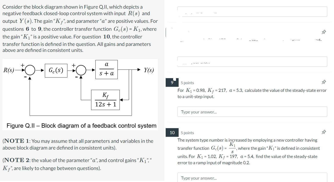
Consider the block diagram shown in Figure Q.II, which depicts a negative feedback closed-loop control system with input \( R(s) \) and output \( Y(s) \). The gain " \( K_{f} \) ", and parameter " \( a \) " are positive values. For questions \( \mathbf{6} \) to \( \mathbf{9} \), the controller transfer function \( G_{c}(s)=K_{1} \), where the gain " \( K_{1} \) " is a positive value. For question \( \mathbf{1 0} \), the controller transfer function is defined in the question. All gains and parameters above are defined in consistent units. Figure Q.II - Block diagram of a feedback control system 10 points The system type number is increased by employing a new controller having transfer function \( G_{c}(s)=\frac{K_{1}}{s} \), where the gain " \( K_{1} \) " is defined in consistent units. For \( K_{1}=1.02, K_{f}=197, a=5.4 \), find the value of the steady-state error to a ramp input of magnitude \( 0.2 \).