Home /
Expert Answers /
Electrical Engineering /
consider-the-single-line-diagram-of-a-power-system-shown-in-figure-3-42-with-equipment-ratin-pa208
(Solved): Consider the single-line diagram of a power system shown in Figure \( 3.42 \) with equipment ratin ...
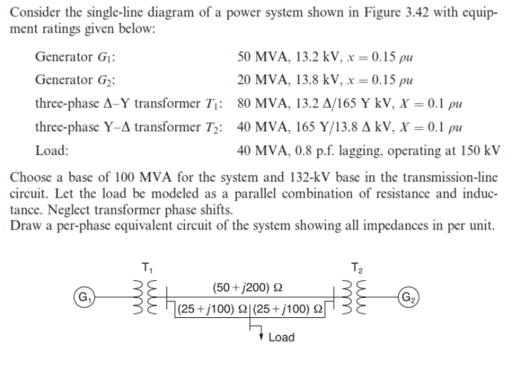
Consider the single-line diagram of a power system shown in Figure \( 3.42 \) with equipment ratings given below: \( \begin{array}{ll}\text { Generator } G_{1}: & 50 \mathrm{MVA}, 13.2 \mathrm{kV}, x=0.15 \rho u \\ \text { Generator } G_{2}: & 20 \mathrm{MVA}, 13.8 \mathrm{kV}, x=0.15 \rho u \\ \text { three-phase } \Delta-\mathrm{Y} \text { transformer } T_{1}: & 80 \mathrm{MVA}, 13.2 \Delta / 165 \mathrm{Y} \mathrm{kV}, X=0.1 \rho u \\ \text { three-phase } \mathrm{Y}-\Delta \text { transformer } T_{2}: & 40 \mathrm{MVA}, 165 \mathrm{Y} / 13.8 \Delta \mathrm{kV}, X=0.1 \rho u \\ \text { Load: } & 40 \mathrm{MVA}, 0.8 \mathrm{p} . f \text {. lagging, operating at } 150 \mathrm{kV}\end{array} \) Choose a base of 100 MVA for the system and 132-kV base in the transmission-line circuit. Let the load be modeled as a parallel combination of resistance and inductance. Neglect transformer phase shifts. Draw a per-phase equivalent circuit of the system showing all impedances in per unit.