Home /
Expert Answers /
Electrical Engineering /
derive-the-open-loop-and-close-loop-transfer-function-model-of-the-qube-servo-2-system-and-create-a-pa884
(Solved): Derive the open loop and close loop transfer function model of the Qube Servo 2 system and create a ...
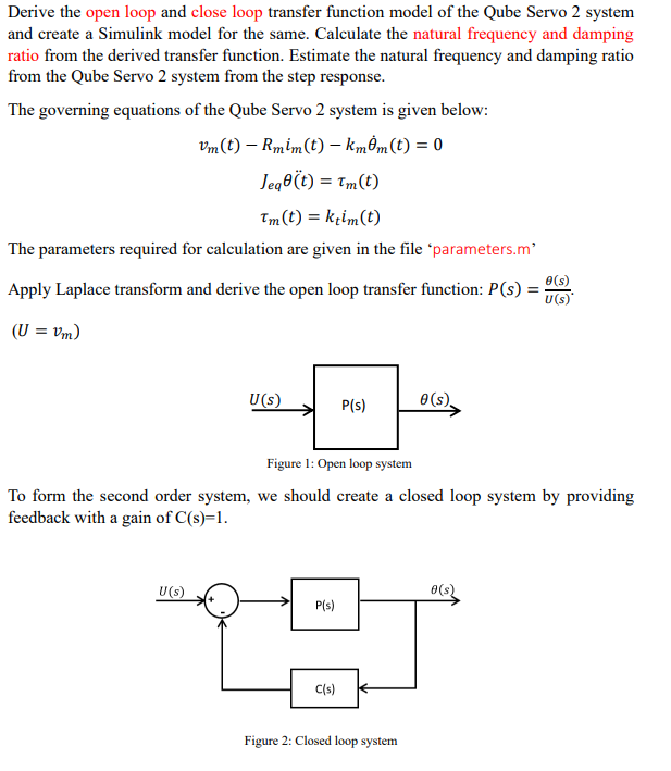
Derive the open loop and close loop transfer function model of the Qube Servo 2 system and create a Simulink model for the same. Calculate the natural frequency and damping ratio from the derived transfer function. Estimate the natural frequency and damping ratio from the Qube Servo 2 system from the step response. The governing equations of the Qube Servo 2 system is given below: The parameters required for calculation are given in the file 'parameters.m' Apply Laplace transform and derive the open loop transfer function: . To form the second order system, we should create a closed loop system by providing feedback with a gain of . Figure 2: Closed loop system
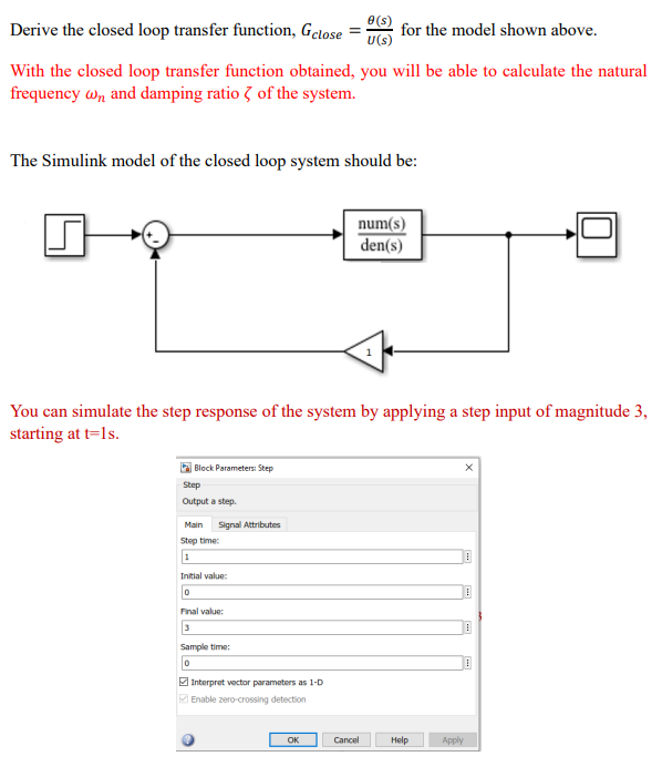
Derive the closed loop transfer function, for the model shown above. With the closed loop transfer function obtained, you will be able to calculate the natural frequency and damping ratio of the system. The Simulink model of the closed loop system should be: You can simulate the step response of the system by applying a step input of magnitude 3 , starting at .
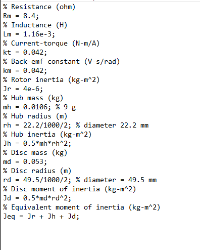
\% Resistance (ohm) Inductance ; \% Current-torque ( -m/A) ; Back-emf constant (V-s/rad) ; Rotor inertia Hub mass Hub radius diameter Hub inertia ; Disc mass ; Disc radius diameter Disc moment of inertia ; Equivalent moment of inertia ;
Expert Answer
To derive the open loop transfer function, we need to apply the Laplace transform to the given gover...