Home /
Expert Answers /
Computer Science /
exercise-1-given-the-datapath-control-diagram-in-figure-1-complete-the-values-expected-at-every-pa534
(Solved): Exercise 1 Given the Datapath & control diagram in Figure 1, complete the values expected at every ...
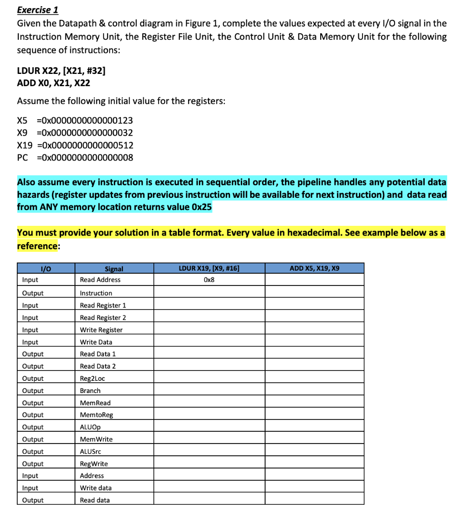
![PC
4-
>Add
Read
address
Instruction
[31-0]
Instruction
memory
Instruction [31-21]
Instruction [9-5]
Instruction [20-16]
Instr](https://media.cheggcdn.com/media/104/104a8075-4171-438f-8aa4-e7425c47be47/phpfo1jM4)
Exercise 1 Given the Datapath & control diagram in Figure 1, complete the values expected at every I/O signal in the Instruction Memory Unit, the Register File Unit, the Control Unit & Data Memory Unit for the following sequence of instructions: LDUR X22, [X21, #32] ADD X0, X21, X22 Assume the following initial value for the registers: X5 =0x0000000000000123 X9 0x0000000000000032 X19 0x0000000000000512 PC =0x0000000000000008 Also assume every instruction is executed in sequential order, the pipeline handles any potential data hazards (register updates from previous instruction will be available for next instruction) and data read from ANY memory location returns value 0x25 You must provide your solution in a table format. Every value in hexadecimal. See example below as a reference: 1/0 Input Output Input Input Input Input Output Output Output Output Output Output Output Output Output Output Input Input Output Signal Read Address Instruction Read Register 1 Read Register 2 Write Register Write Data Read Data 1 Read Data 2 Reg2Loc Branch Mem Read MemtoReg ALUOP MemWrite ALUSrc RegWrite Address Write data Read data LDUR X19, [X9, #16] 0x8 ADD X5, X19, X9
PC 4- >Add Read address Instruction [31-0] Instruction memory Instruction [31-21] Instruction [9-5] Instruction [20-16] Instruction [4-0] Instruction [31-0] Control Reg2Loc Branch MemRead MemtoReg ALUOP MemWrite ALUSrc RegWrite Read register 1 Read data 1 Read register 2 32 Write register Read data 2 Write data Registers Sign- extend 64 Instruction [31-21] Shift left 2 MUX 1 ALU Addresult Zero ALU ALU result ALU control Figure 1 Datapath and Control Diagram 0 Read Address data Write Data data memory
Expert Answer
Instruction Memory Unit LDUR ADD STUR Input ReadAddress 00000000000000000000000000000100 000000000000000000000000000010