Home /
Expert Answers /
Electrical Engineering /
experiment-2-rl-circuit-build-the-rl-circuit-shown-in-fig-2-set-the-amplitude-of-the-source-at-5-pa573
(Solved): Experiment 2. RL Circuit Build the RL circuit shown in Fig. 2. Set the amplitude of the source at 5 ...
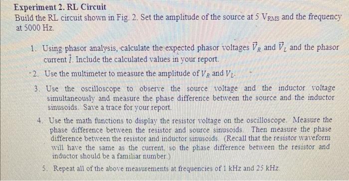
Experiment 2. RL Circuit Build the RL circuit shown in Fig. 2. Set the amplitude of the source at 5 VRMs and the frequency at 5000 Hz. 1. Using phasor analysis, calculate the expected phasor voltages VR and V, and the phasor current 1. Include the calculated values in your report. -2. Use the multimeter to measure the amplitude of VR and V - 3. Use the oscilloscope to observe the source voltage and the inductor voltage simultaneously and measure the phase difference between the source and the inductor sinusoids. Save a trace for your report. 4. Use the math functions to display the resistor voltage on the oscilloscope. Measure the phase difference between the resistor and source sinusoids. Then measure the phase difference between the resistor and inductor sinusoids. (Recall that the resistor waveform will have the same as the current, so the phase difference between the resistor and inductor should be a familiar number) 5. Repeat all of the above measurements at frequencies of 1 kHz and 25 kHz.
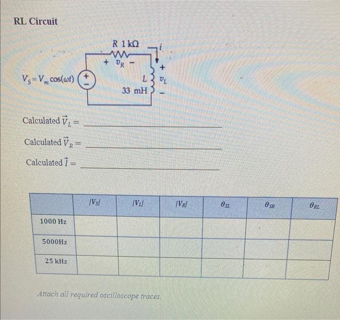
RL Circuit Riko + OR VsVcos(wt) VL L 33 mH Calculated 7. = Calculated VR = Calculated 1 = Vs! /V2/ TV/ sz SR ORL 1000 Hz 5000Hz 25 kHz Attach all required oscilloscope traces.