Home /
Expert Answers /
Electrical Engineering /
figure-1-a-a-self-bissed-bjt-b-a-self-biased-bjt-with-emitter-degeneration-c-a-resistivediv-pa219
(Solved): Figure 1: (a) A self-bissed BJT. (b) A self-biased BJT with emitter degeneration. (c) A resistivediv ...
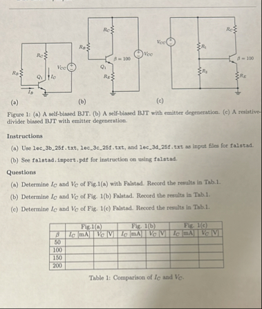
Figure 1: (a) A self-bissed BJT. (b) A self-biased BJT with emitter degeneration. (c) A resistivedivider binsed BJT with emitter degeneration. Instructions (a) Use lec_3b_25f.txt, lec_3c_25f.txt, and lec_3d_25f.txt as input files for falstad. (b) See falstad.import.pdf for instruction on using falstad. Questions (a) Determine
I_(C)and
V_(C)of Fig.1(a) with Falstad. Record the results in Tab.1. (b) Determine
I_(C)and
V_(C)of Fig. 1(b) Falstad. Record the results in Tab.1. (c) Determine
I_(C)and
V_(C)of Fig. 1(c) Falstad. Record the results in Tab.1. \table[[,Fig. 1(a),Fig. 1(b),Fig. I(c)],[
\beta ,
I_(c)[mA],,
I_(c)[mA],
V_(c)[V],,[
:V_(c)|V|