Home /
Expert Answers /
Computer Science /
following-table-shows-the-state-table-for-a-sequential-circuit-3-marks-a-nbsp-draw-the-state-pa551
(Solved): Following table shows the state table for a sequential circuit. (3 marks) (a) Draw the state ...
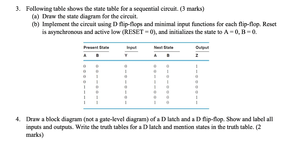
Following table shows the state table for a sequential circuit. (3 marks)
(a) Draw the state diagram for the circuit.
(b) Implement the circuit using D flip-flops and minimal input functions for each flip-flop. Reset
is asynchronous and active low (RESET = 0), and initializes the state to A = 0, B = 0.
Draw a block diagram (not a gate-level diagram) of a D latch and a D flip-flop. Show and label all inputs and outputs. Write the truth tables for a D latch and mention states in the truth table. (2 marks)
PLEASE ANSWER ASAP
3. Following table shows the state table for a sequential circuit. ( 3 marks) (a) Draw the state diagram for the circuit. (b) Implement the circuit using D flip-flops and minimal input functions for each flip-flop. Reset is asynchronous and active low (RESET \( =0 \) ), and initializes the state to \( \mathrm{A}=0, \mathrm{~B}=0 \). 4. Draw a block diagram (not a gate-level diagram) of a D latch and a D flip-flop. Show and label all inputs and outputs. Write the truth tables for a D latch and mention states in the truth table. (2 marks)
Expert Answer
Solution:- STEP 1:- Draw the state diagram for the circuit. State diagram for the circuit:- A state diagram is a type used in computer science and rel