Home /
Expert Answers /
Mechanical Engineering /
for-the-single-link-robot-arm-system-given-in-figure-1-mass-of-the-system-is-m-and-length-is-l-pa427
(Solved): For the single link robot arm system given in Figure 1 mass of the system is m, and length is l ...
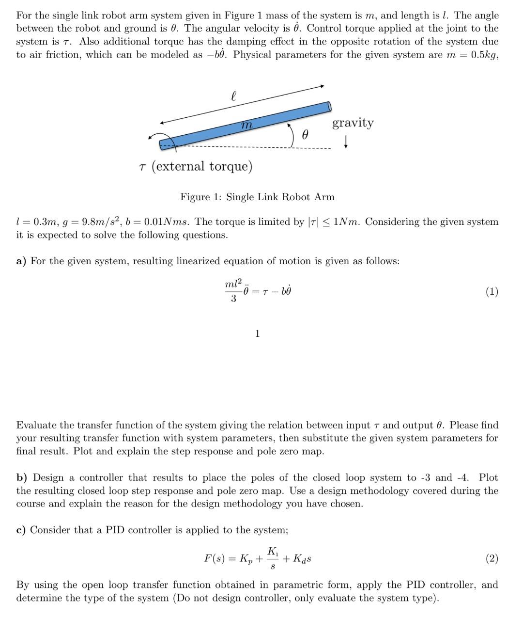
For the single link robot arm system given in Figure 1 mass of the system is , and length is . The angle between the robot and ground is . The angular velocity is . Control torque applied at the joint to the system is . Also additional torque has the damping effect in the opposite rotation of the system due to air friction, which can be modeled as . Physical parameters for the given system are , Figure 1: Single Link Robot Arm . The torque is limited by . Considering the given system it is expected to solve the following questions. a) For the given system, resulting linearized equation of motion is given as follows: 1 Evaluate the transfer function of the system giving the relation between input and output . Please find your resulting transfer function with system parameters, then substitute the given system parameters for final result. Plot and explain the step response and pole zero map. b) Design a controller that results to place the poles of the closed loop system to -3 and -4 . Plot the resulting closed loop step response and pole zero map. Use a design methodology covered during the course and explain the reason for the design methodology you have chosen. c) Consider that a PID controller is applied to the system; By using the open loop transfer function obtained in parametric form, apply the PID controller, and determine the type of the system (Do not design controller, only evaluate the system type).