Home /
Expert Answers /
Electrical Engineering /
model-the-circuit-in-figure-1-on-multisim-and-adjust-the-input-sine-wave-of-v1-peak-determine-t-pa684
(Solved): Model the circuit in Figure 1 on Multisim and adjust the input sine wave of V1 peak. Determine t ...
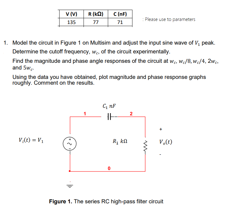
Model the circuit in Figure 1 on Multisim and adjust the input sine wave of peak. Determine the cutoff frequency, , of the circuit experimentally. Find the magnitude and phase angle responses of the circuit at , and . Using the data you have obtained, plot magnitude and phase response graphs roughly. Comment on the results. Figure 1. The series high-pass filter circuit
Expert Answer
Solution:Step 1:To design and analyze a high-pass RC filter circuit using Multisim, follow these steps:Open Multisim and create a new blank schematic.Place a voltage source (V1) in the schematic and set its peak voltage to 135V. Connect the positive terminal of V1 to the circuit.Place a resistor (R) with a value of 77k? and a capacitor (C) with a value of 71nF in the circuit. Connect one end of the resistor to the positive terminal of V1, and connect the other end of the resistor to one end of the capacitor. Connect the other end of the capacitor to the ground.Place a voltage probe in the circuit to measure the voltage across the capacitor (VC).