Home /
Expert Answers /
Electrical Engineering /
multisim-fig-1-objective-to-review-impedance-and-power-calculations-of-reactive-circuits-and-des-pa221
(Solved): Multisim Fig. 1 Objective: To review impedance and power calculations of reactive circuits and des ...
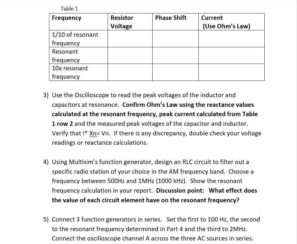
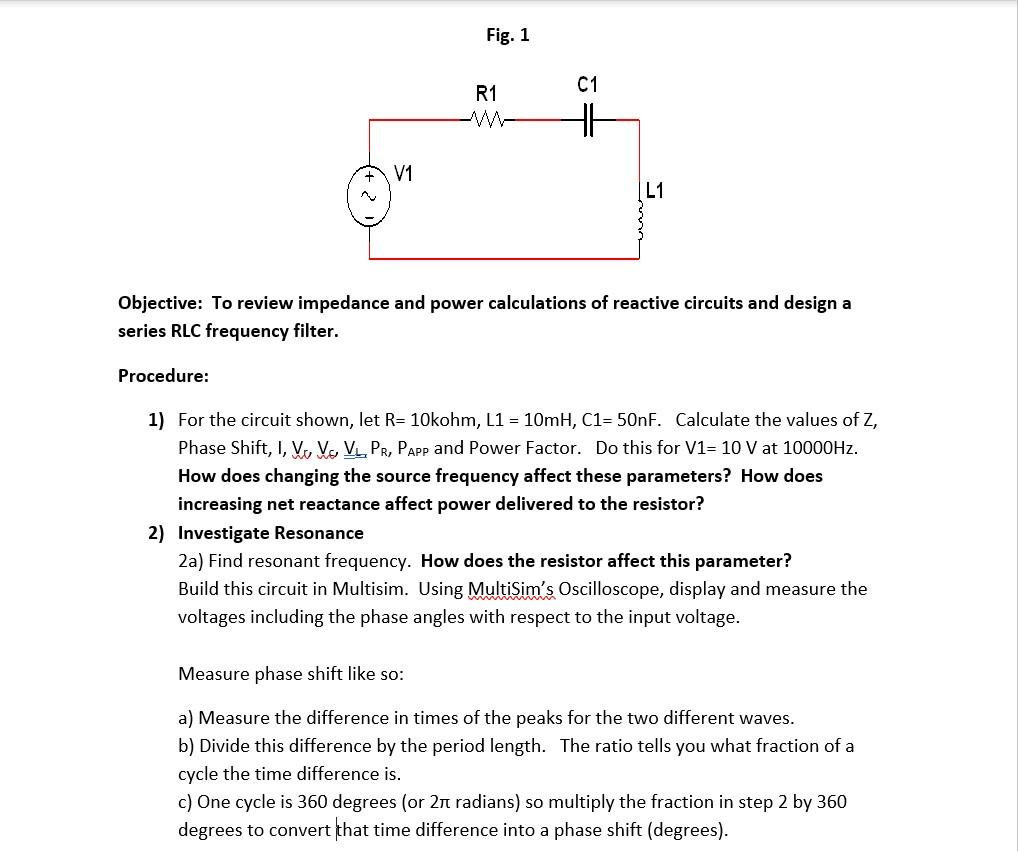
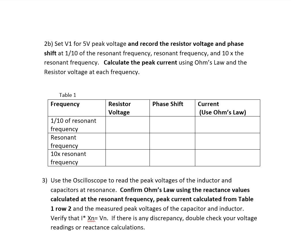
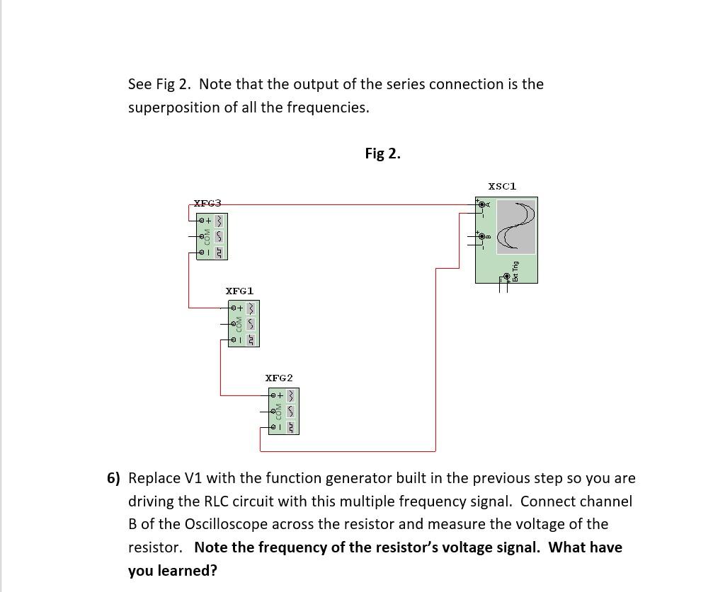
Fig. 1 Objective: To review impedance and power calculations of reactive circuits and design a series RLC frequency filter. Procedure: 1) For the circuit shown, let \( R=10 \mathrm{kohm}, \mathrm{L} 1=10 \mathrm{mH}, \mathrm{C} 1=50 \mathrm{nF} \). Calculate the values of \( Z \), Phase Shift, I, \( \mathrm{V}_{J}, \mathrm{~V}_{\sigma}, \underline{V}_{\mathrm{L}}, P_{R}, P_{\text {APP }} \) and Power Factor. Do this for \( \mathrm{V} 1=10 \mathrm{~V} \) at \( 10000 \mathrm{~Hz} \). How does changing the source frequency affect these parameters? How does increasing net reactance affect power delivered to the resistor? 2) Investigate Resonance 2a) Find resonant frequency. How does the resistor affect this parameter? Build this circuit in Multisim. Using MultiSim's Oscilloscope, display and measure the voltages including the phase angles with respect to the input voltage. Measure phase shift like so: a) Measure the difference in times of the peaks for the two different waves. b) Divide this difference by the period length. The ratio tells you what fraction of a cycle the time difference is. c) One cycle is 360 degrees (or \( 2 \pi \) radians) so multiply the fraction in step 2 by 360 degrees to convert that time difference into a phase shift (degrees).
2b) Set V1 for \( 5 \mathrm{~V} \) peak voltage and record the resistor voltage and phase shift at \( 1 / 10 \) of the resonant frequency, resonant frequency, and \( 10 \mathrm{x} \) the resonant frequency. Calculate the peak current using Ohm's Law and the Resistor voltage at each frequency. 3) Use the Oscilloscope to read the peak voltages of the inductor and capacitors at resonance. Confirm Ohm's Law using the reactance values calculated at the resonant frequency, peak current calculated from Table 1 row 2 and the measured peak voltages of the capacitor and inductor. Verify that \( \mathrm{I}^{*} \mathrm{Xn}=\mathrm{Vn} \). If there is any discrepancy, double check your voltage readings or reactance calculations.
3) Use the Oscilloscope to read the peak voltages of the inductor and capacitors at resonance. Confirm Ohm's Law using the reactance values calculated at the resonant frequency, peak current calculated from Table 1 row 2 and the measured peak voltages of the capacitor and inductor. Verify that \( \mathrm{I}^{*} \mathbf{X} \mathrm{n}=\mathrm{Vn} \). If there is any discrepancy, double check your voltage readings or reactance calculations. 4) Using Multisim's function generator, design an RLC circuit to filter out a specific radio station of your choice in the \( \mathrm{AM} \) frequency band. Choose a frequency between \( 500 \mathrm{~Hz} \) and \( 1 \mathrm{MHz}(1000 \mathrm{kHz}) \). Show the resonant frequency calculation in your report. Discussion point: What effect does the value of each circuit element have on the resonant frequency? 5) Connect 3 function generators in series. Set the first to \( 100 \mathrm{~Hz} \), the second to the resonant frequency determined in Part 4 and the third to \( 2 \mathrm{MHz} \). Connect the oscilloscope channel A across the three \( A C \) sources in series.
See Fig 2. Note that the output of the series connection is the superposition of all the frequencies. Fig 2. 6) Replace V1 with the function generator built in the previous step so you are driving the RLC circuit with this multiple frequency signal. Connect channel \( B \) of the Oscilloscope across the resistor and measure the voltage of the resistor. Note the frequency of the resistor's voltage signal. What have you learned?