Home /
Expert Answers /
Electrical Engineering /
part-a-calculating-the-output-voltage-of-a-noninverting-op-amp-circuit-for-the-circuit-shown-figu-pa750
(Solved): Part A - Calculating the output voltage of a noninverting op-amp circuit For the circuit shown(Figu ...
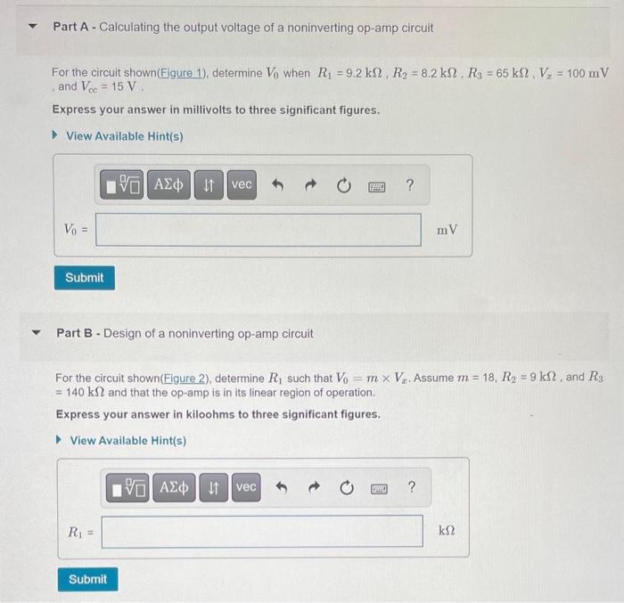
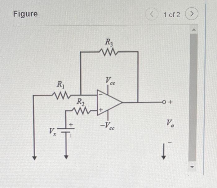
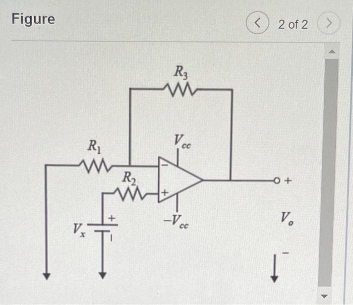
Part A - Calculating the output voltage of a noninverting op-amp circuit For the circuit shown(Figure 1), determine \( V_{0} \) when \( R_{1}=9.2 \mathrm{k} \Omega, R_{2}=8.2 \mathrm{k} \Omega, R_{3}=65 \mathrm{k} \Omega, V_{x}=100 \mathrm{mV} \) , and \( V_{c c}=15 \mathrm{~V} \). Express your answer in millivolts to three significant figures. Part B - Design of a noninverting op-amp circuit For the circuit shown(Figure 2), determine \( R_{1} \) such that \( V_{0}=m \times V_{x} \). Assume \( m=18, R_{2}=9 \mathrm{k} \Omega \), and \( R_{3} \) \( =140 \mathrm{k} \Omega \) and that the op-amp is in its linear region of operation. Express your answer in kiloohms to three significant figures.
Figure 1 of 2
2 of 2