(Solved): Please derive the closed loop transfer function with the output being the position of the motor the ...
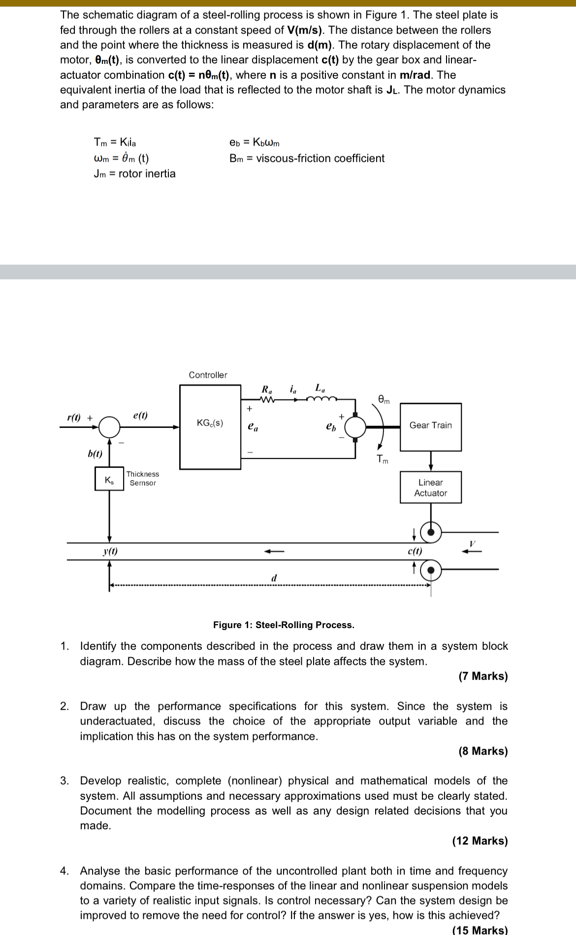
Please derive the closed loop transfer function with the output being the position of the motor theta. Then indicate how to compensate for the thickness sensor Ks in the closed loop transfer function. The schematic diagram of a steel-rolling process is shown in Figure 1. The steel plate is fed through the rollers at a constant speed of
V((m)/(s)). The distance between the rollers and the point where the thickness is measured is
d(m). The rotary displacement of the motor,
\theta _(m)(t), is converted to the linear displacement
c(t)by the gear box and linearactuator combination
c(t)=n\theta _(m)(t), where
nis a positive constant in
(m)/(r)ad. The equivalent inertia of the load that is reflected to the motor shaft is
JL. The motor dynamics and parameters are as follows:
T_(m)=K_(il),e_(b)=K_(b)\omega _(m)
\omega _(m)=\theta _(m)^(˙)(t),B_(m)= viscous-friction coefficient
J_(m)= rotor inertia
Figure 1: Steel-Rolling Process. Identify the components described in the process and draw them in a system block diagram. Describe how the mass of the steel plate affects the system. (7 Marks) Draw up the performance specifications for this system. Since the system is underactuated, discuss the choice of the appropriate output variable and the implication this has on the system performance. (8 Marks) Develop realistic, complete (nonlinear) physical and mathematical models of the system. All assumptions and necessary approximations used must be clearly stated. Document the modelling process as well as any design related decisions that you made. (12 Marks) Analyse the basic performance of the uncontrolled plant both in time and frequency domains. Compare the time-responses of the linear and nonlinear suspension models to a variety of realistic input signals. Is control necessary? Can the system design be improved to remove the need for control? If the answer is yes, how is this achieved? (15 Marks)