Home /
Expert Answers /
Electrical Engineering /
please-do-answer-the-table-and-test-your-knowledge-1-amp-2-thankyouuuuu-nbsp-activity-no-9-po-pa765
(Solved): please do answer the TABLE and test your knowledge 1 & 2 thankyouuuuu ACTIVITY No. 9 PO ...
please do answer the TABLE and test your knowledge 1 & 2
thankyouuuuu
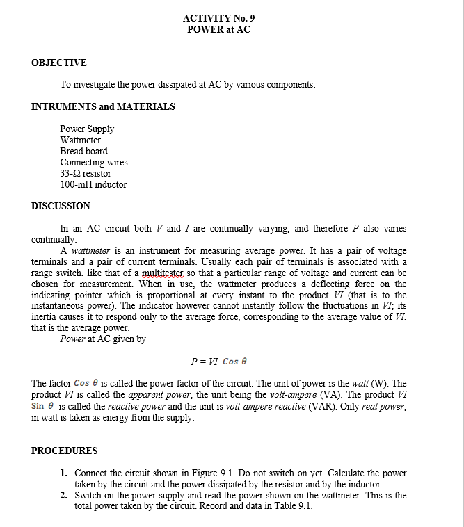
ACTIVITY No. 9 POWER at AC OBJECTIVE To investigate the power dissipated at AC by various components. INTRUMENTS and MATERIALS Power Supply Wattmeter Bread board Connecting wires 33-92 resistor 100-mH inductor DISCUSSION In an AC circuit both V and I are continually varying, and therefore P also varies continually. A wattmeter is an instrument for measuring average power. It has a pair of voltage terminals and a pair of current terminals. Usually each pair of terminals is associated with a range switch, like that of a multitester so that a particular range of voltage and current can be chosen for measurement. When in use, the wattmeter produces a deflecting force on the indicating pointer which is proportional at every instant to the product VI (that is to the instantaneous power). The indicator however cannot instantly follow the fluctuations in VI; its inertia causes it to respond only to the average force, corresponding to the average value of VI, that is the average power. Power at AC given by P = VI Cos 0 The factor Cose is called the power factor of the circuit. The unit of power is the watt (W). The product VI is called the apparent power, the unit being the volt-ampere (VA). The product VI Sin is called the reactive power and the unit is volt-ampere reactive (VAR). Only real power, in watt is taken as energy from the supply. PROCEDURES 1. Connect the circuit shown in Figure 9.1. Do not switch on yet. Calculate the power taken by the circuit and the power dissipated by the resistor and by the inductor. 2. Switch on the power supply and read the power shown on the wattmeter. This is the total power taken by the circuit. Record and data in Table 9.1.
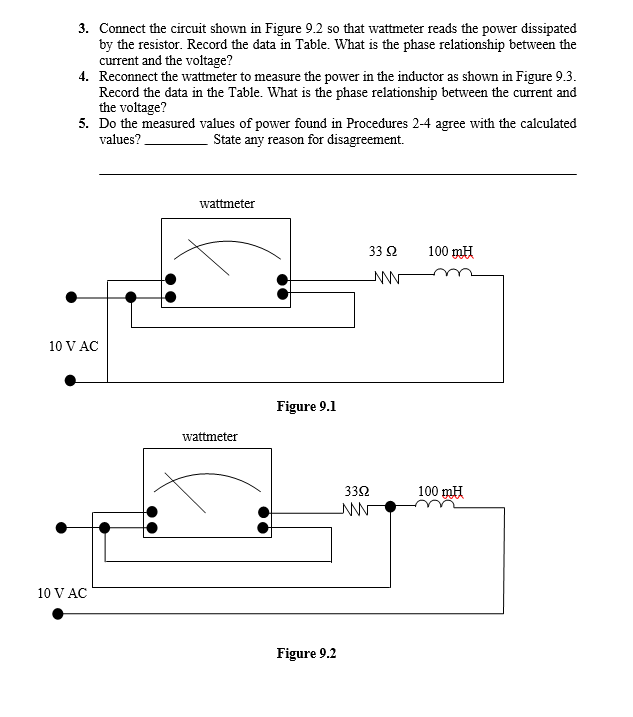
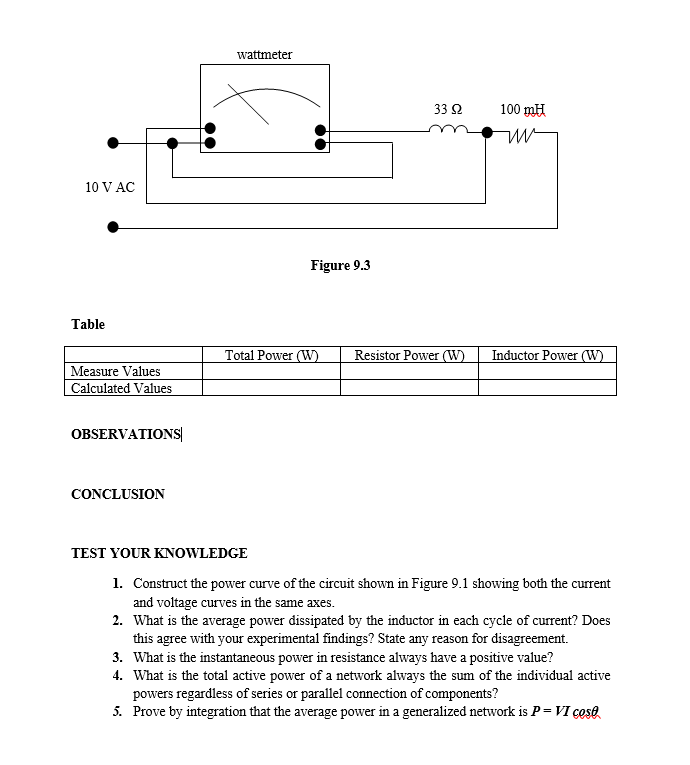
3. Connect the circuit shown in Figure 9.2 so that wattmeter reads the power dissipated by the resistor. Record the data in Table. What is the phase relationship between the current and the voltage? 4. Reconnect the wattmeter to measure the power in the inductor as shown in Figure 9.3. Record the data in the Table. What is the phase relationship between the current and the voltage? 5. Do the measured values of power found in Procedures 2-4 agree with the calculated values? State any reason for disagreement. wattmeter 33 S2 100 mH NNN 10 V AC 10 V AC wattmeter Figure 9.1 Figure 9.2 3392 ANN 100 mH
wattmeter 10 V AC 100 mH Table Resistor Power (W) Inductor Power (W) Measure Values Calculated Values OBSERVATIONS CONCLUSION TEST YOUR KNOWLEDGE 1. Construct the power curve of the circuit shown in Figure 9.1 showing both the current and voltage curves in the same axes. 2. What is the average power dissipated by the inductor in each cycle of current? Does this agree with your experimental findings? State any reason for disagreement. 3. What is the instantaneous power in resistance always have a positive value? 4. What is the total active power of a network always the sum of the individual active powers regardless of series or parallel connection of components? 5. Prove by integration that the average power in a generalized network is P = VI cost Figure 9.3 Total Power (W) 33 92