Home /
Expert Answers /
Electrical Engineering /
problem-1-2-2-2-2-2-mathrm-pts-show-a-truth-table-for-each-of-the-following-circuits-a-pa242
(Solved): Problem 1: \( (2+2+2+2+2 \mathrm{pts}) \) Show a truth table for each of the following circuits: a ...
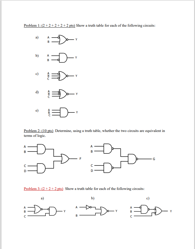

Problem 1: \( (2+2+2+2+2 \mathrm{pts}) \) Show a truth table for each of the following circuits: a) b) c) d) e) Problem 2: (10 pts) Determine, using a truth table, whether the two circuits are equivalent in terms of logic. Problem 3: \( (2+2+2 \) pts \( ) \) Show a truth table for each of the following circuits:
Problem 4: ( \( 10 \mathrm{pts}) \) You are asked to build a digital logic circuit for a security alarm system. The system has four Motion Sensors which indicate the presence of an intruder. Each individual motion sensor should be able to trigger an alarm. The system should be completely disabled via a Master Switch. In addition, the siren, the flashlight and the automated call to the security company should have separate enable switches. The inputs and outputs are specified as follows: Inputs: \( \mathrm{S}_{1}, \mathrm{~S}_{2}, \mathrm{~S}_{3}, \mathrm{~S}_{4}: \) Motion Sensors ( \( 0= \) no intrusion detected, \( 1= \) intrusion detected) M : Master Switch ( \( 0= \) security system disabled, \( 1= \) security system enabled) A : Audible Alarm Enable Switch \( (0= \) audible alarm disabled, 1 = audible alarm enabled) L : Light Enable Switch ( \( 0= \) flash light disabled, \( 1= \) flash light enabled \( ) \) P : Phone Call Enable Switch ( 0 = call disabled, \( 1= \) call enabled) Outputs: B : Alarm Buzzer F : Flash Light C :Call Box Draw the logic circuit diagram of the digital logic using AND and OR gates and inverters. Problem 5: (10 pts) The security alarm system you designed in Problem 4 has an issue that it accidentally gets triggered by pets. You consider improving the system by triggering an alarm only if at least two motion sensors are activated at the same time. Show a truth table that has the four motion sensors as inputs and an alarm trigger as the output which shows how to implement the improved security system design. Problem 6: (5 pts) Design a 4-input XOR gate circuit that outputs a 1 if the number of 1 's on the four inputs \( \mathrm{A}, \mathrm{B}, \mathrm{C}, \mathrm{D} \) is odd. Problem 7: (10 pts) Design a Minority gate for three inputs. The output of such a gate becomes 1 if a smaller number of inputs is 1 than 0 . Show a truth table and a logic gate implementation using AND and OR gates and inverters. Problem 8: (10 pts) Construct the truth table for the following circuit: b)