Home /
Expert Answers /
Electrical Engineering /
problem-2-the-circuit-shown-in-figure-2-is-used-as-a-bias-circuit-in-analog-cmos-integrated-circui-pa526
(Solved): Problem 2. The circuit shown in Figure 2 is used as a bias circuit in analog CMOS integrated circui ...
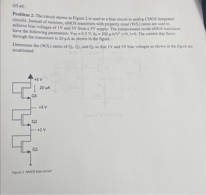
Problem 2. The circuit shown in Figure 2 is used as a bias circuit in analog CMOS integrated circuits. Instead of resistors, nMOS transistors with properly sized (W/L) ratios are used to achieve bias voltages of and from a supply. The enhancement-mode nMOS transistors have the following parameters; . The current that flows through the transistors is as shown in the figure. Determine the (W/L) ratios of , and so that and bias voltages as shown in the figure are established.
Expert Answer
when any mosfet is shorted from Vd toVg, then mosfet always in satration mode.like, for MOSFET to be in saturation.