Home /
Expert Answers /
Electrical Engineering /
problem-4-a-bandpass-filter-composed-of-an-rlc-circuit-is-shown-in-the-figure-g-s-v-out-s-v-pa454
(Solved): Problem 4 A bandpass filter composed of an RLC circuit is shown in the figure. G(s)=(V_(out )(s))/(V ...
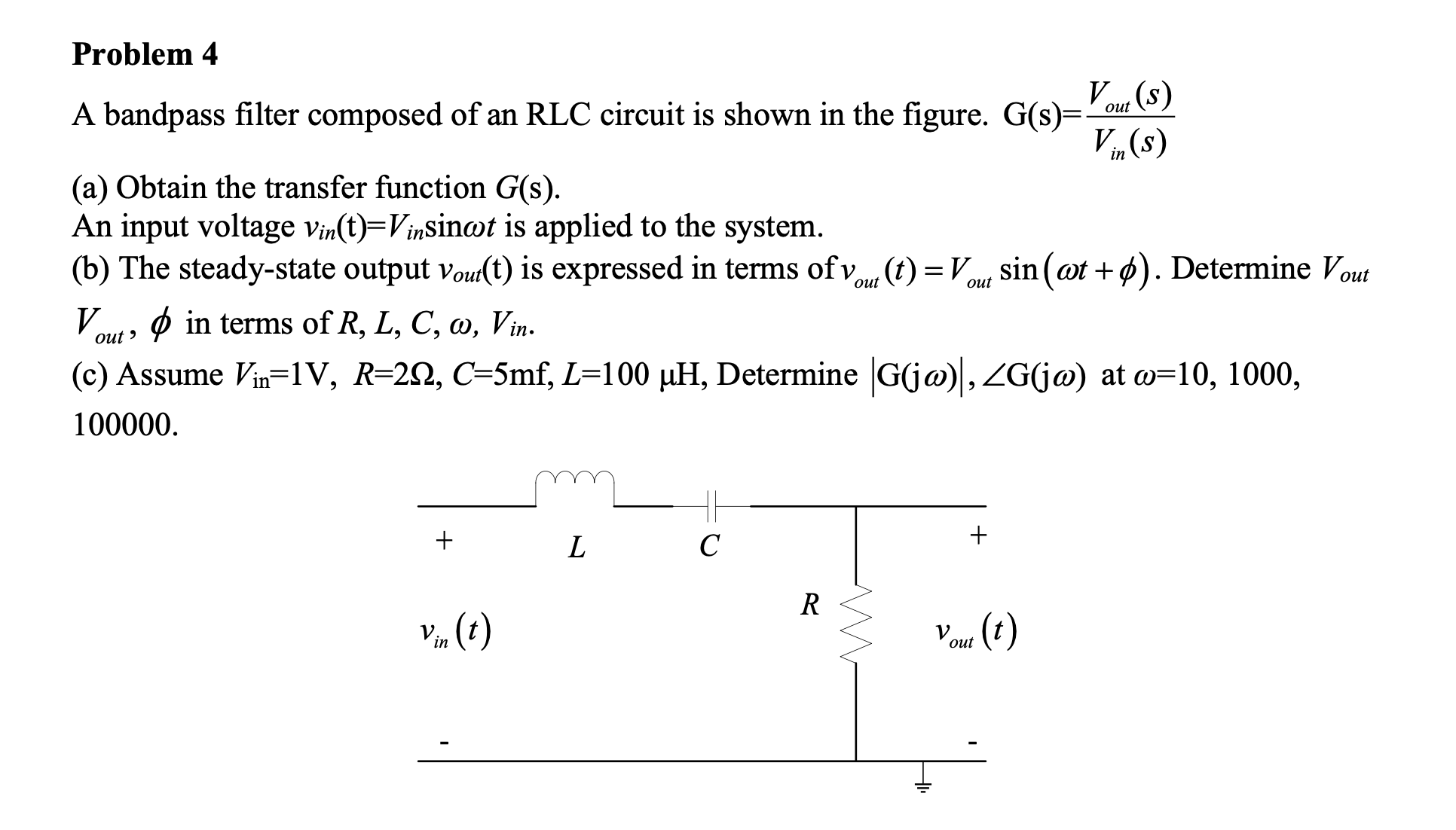
Problem 4
A bandpass filter composed of an RLC circuit is shown in the figure. G(s)=(V_(out )(s))/(V_(in )(s))
(a) Obtain the transfer function G(s).
An input voltage v_(in)(t)=V_(in)sin\omega t is applied to the system.
(b) The steady-state output v_(out )(t) is expressed in terms of v_(out )(t)=V_(out )sin(\omega t+\phi ). Determine V_(out )
V_(out ),\phi in terms of R,L,C,\omega ,V_(in ).
(c) Assume V_(in)=1V,R=2\Omega ,C=5mf,L=100\mu H, Determine |G(j\omega )|(,)/(_(G))(j\omega ) at \omega =10,1000,