Home /
Expert Answers /
Electrical Engineering /
procedure-figurel-1-connect-the-function-generator-to-mathrm-cro-and-set-mathrm-v-pa334
(Solved): Procedure: Figurel 1. Connect the function generator to \( \mathrm{CRO} \) and set \( \mathrm{V}_{\ ...
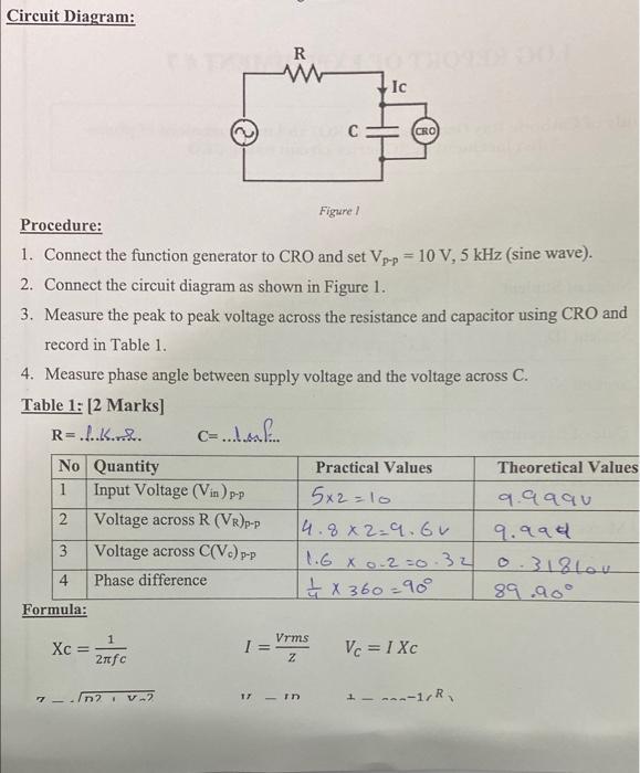
Procedure: Figurel 1. Connect the function generator to \( \mathrm{CRO} \) and set \( \mathrm{V}_{\mathrm{p}-\mathrm{p}}=10 \mathrm{~V}, 5 \mathrm{kHz} \) (sine wave). 2. Connect the circuit diagram as shown in Figure 1. 3. Measure the peak to peak voltage across the resistance and capacitor using CRO and record in Table 1. 4. Measure phase angle between supply voltage and the voltage across \( \mathrm{C} \). Table 1: [2 Marks] \[ R=.1 . k \text {.n. } \quad C=\ldots \ldots f . . \] Formuia: \[ \mathrm{Xc}=\frac{1}{2 \pi f c} \quad I=\frac{V r m s}{z} \quad V_{C}=I X C \] \[ 7-\sqrt{n \eta \cdot v_{n}} \quad v-i n \quad+\ldots{ }^{n} r^{R} \]
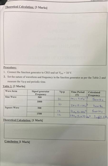
Procedure: 1. Connect the function generator to \( \mathrm{CRO} \) and set \( \mathrm{V}_{P P}=10 \mathrm{~V} \). 2. Set the nature of waveform and frequency in the function gencrator as per the Table 2 and measure the \( V_{\mathrm{p}}-\mathrm{p} \) and periodic time. Table 2: [2 Marks] Theoretical Calculation: [1 Mark]
Expert Answer
Since CRO waveform is not given so that we cannot find theoretical value of input voltage. Voltage across R, by Voltage division rule, VR=RR?jXc×VinXc