Home /
Expert Answers /
Mechanical Engineering /
project-fault-tree-and-event-tree-analysis-consider-that-your-hazard-analysis-process-resulted-in-pa144
(Solved): Project: Fault Tree and Event Tree Analysis Consider that your hazard analysis process resulted in ...
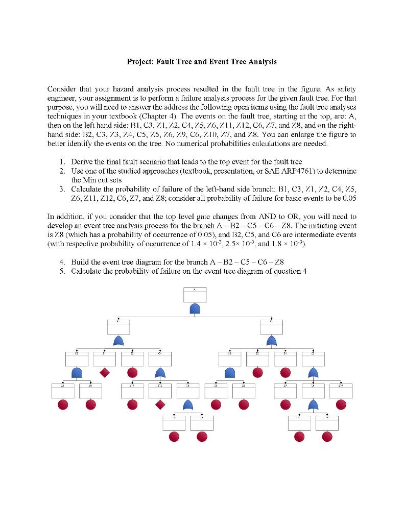

Project: Fault Tree and Event Tree Analysis Consider that your hazard analysis process resulted in the fault tree in the figure. As safety engineer, your assignment is to perform a failure analysis process for the given fault tree. For that purpose, you will need to answer the address the following open items using the fault tree analyses techniques in your textbook (Chapter 4). The events on the fault tree, starting at the top, are: A, then on the left hand side: B1, C3, 71, 72, C4, 75, 76, 711, 712, C6, 77, and Z8, and on the right- hand side: 132, C3, 73, 74, C5, 75, 76, 79, C6, Z10, Z7, and 78. You can enlarge the figure to better identify the events on the tree. No numerical probabilities calculations are needed. 1. Derive the final fault scenario that leads to the top event for the fault tree 2. Use one of the studied approaches (textbook, presentation, or SAE ARP4761) to determine the Min cut sets 3. Calculate the probability of failure of the left-hand side branch: B1, C3, 71, 72, C4, 75, 26, 211, 212, C6, 27, and Z8; consider all probability of failure for basic events to be 0.05 In addition, if you consider that the top level gate changes from AND to OR, you will need to develop an event tree analysis process for the branch A-B2-C5-C6-Z8. The initiating event is 7.8 (which has a probability of occurrence of 0.05), and 132, C5, and C6 are intermediate events (with respective probability of occurrence of 1.4 x 10², 2.5x 10, and 1.8 × 10-³). 4. Build the event tree diagram for the branch A-B2-C5-C6-28 5. Calculate the probability of failure on the event tree diagram of question 4
Fault tree analysis 4 The greatest of faults, I should say, is to be conscious of none. Thomas Carlyle (1795-1881) 4.1 Introduction A system is a collection of components in a defined architecture with the sole pur- pose of accomplishing that system's function (refer to Fig. 3.1). The functional failure probability of that function is determined by the integrity of the constituent compo- nents as well as the logic of the systems' architecture. The more complex the system, the more there is a need for an in-depth analysis technique to identify all possible combinations of failure that could result in loss of the system's integrity. The Fault Tree Analysis (FTA) is such a technique. A fault tree¹ shows graphically, by means of a specified notation, the logical relationship between a particular system failure and all its contributing causes. This chapter considers the manner in which an FTA is used to show how an unde- sirable top-level failure (or event) may occur via the combination(s) of individual contributing failures, events and/or errors. In doing so, this chapter provides a simple process (in Fig. 4.1) on how to approach and manage the FTA process. The reader is encouraged to review the reference material for more specialist details on the intrica- cies of drawing an actual fault tree. 4.1.1 Background The FTA is a diagrammatic² analytical technique that is used for Reliability, Maintain- ability and Safety Analysis. It is a top-down³ (deductive) analysis, proceeding through successively more detailed (i.e. lower) levels of the design until the probability of occurrence of the top event (the feared event) can be predicted in the context of its environment and operation. 'The term 'tree' is used because the diagrammatic representation of the analysis has a branching structure which increases in size as various levels of details are considered. In fact the structure is more analogous to the roots of a tree, since the normal convention for constructing a fault tree is to start at the top of the page with the consequence' or system failure mode being considered, then represent underneath the causes which could lead to the 'consequence', in increasing details as one progresses down the page. 2 It is a graphic 'model' (consisting of gates and events) of the pathways within a system that can lead to a foreseeable event. The causes of the top event are 'connected' through logic gates and modelling of the corresponding system. 3 A fault tree is a cause-and-effect network. t starts by assuming a system failure mode (the top event) and works backwards (i.e. the opposite to FMECA) to identify the possible causes of this. Aircraft System Safety. http://dx.doi.org/10.1016/3978-0-88-100589-8.06004-0 Copyright © 2017 Duane Kritzinger. Published by Elsevier Ltd. All rights reserved.
60 Aircraft System Safety According to Clemens (2002) and Javadi et al. (2011), the FTA was initially used in 1962 for the US Air Force by Bell Telephone Laboratories on the Minuteman Weapon System¹ (Eckberg, 1964). Since then, the technique has been adopted and adapted by many companies who are interested in reliability engineering. FTA received extensive coverage at a 1965 System Safety Symposium in Seattle sponsored by Boeing and the University of Washington. Boeing began using FTA for civil aircraft design around 1966 (Hixebbauch, 1968). Subsequently within the US military, application of FTA for use with fuses was explored by Picatinny Arsenal in the 1960s and 1970s (Larsen, 1974). In 1976, the US Army Material Command incorporated FTA into the Engineering Design Handbook, Design for Reliability (Evans, 1976). The Reliability Analysis Center at Rome Laboratory, and its successor organisations (now the Defense Systems Information Analysis Center), has published documents on FTA and reliability block diagrams since the 1960s [Chapter 6 (FTA) in MIL-HDBK-338B (Electronic Reliability Design Handbook)]. In 1970, the US Federal Aviation Administration (FAA) published a change to 14 CFR25.1309 airworthiness regulations for transport category aircraft in the Federal Register [FR 5665 (1970-04-08)]. This change adopted failure probability criteria for aircraft systems and equipment and led to widespread use of FTA in civil aviation (Haroonbadi and Haghifam, 2009). In 1998, the FAA published Order 8040.4 establishing risk management policy and hazard analysis in a range of critical activities beyond aircraft certification, including air traffic control and modernisation of the US National Airspace System. This led to the publication of the FAA System Safety Handbook, which describes the use of FTA in various types of formal hazard analysis. Today the FTA methodology is widely used in system safety and reliability engineering, and in all major fields of engineering. It is described in several industry and govern- ment standards, including NUREG-0492, SAE ARP4761, MIL-HDBK-338B, and IEC 61025. 4.1.2 Aim of the Fault Tree Analysis Any sufficiently complex system is subject to failure as a result of one or more subsys- tems or components failing. The aim of the FTA is to use deductive' logic to under- stand all the underlying causes of a particular failure in a sufficiently complex system so that the likelihood of failure can be reduced through improved system design (i.e. different component selection, more stringent development assurance levels and/or via system architectural improvements). 4 Minuteman was a revolutionary concept and an extraordinary technical achievement. Both the missile and basing components incorporated significant advances beyond the relatively slow-reacting, liquid-fuelled, remotely controlled intercontinental ballistic missiles of the previous generation. 5 See http://www.pica.army.mil/Picatinny/. 6 System Safety Handbook. Federal Aviation Administration, 30 December 2000. 7 FTA is a top-down, deductive failure analysis in which an undesired state of a system is analysed using Boolean logic to combine a series of lower-level events.
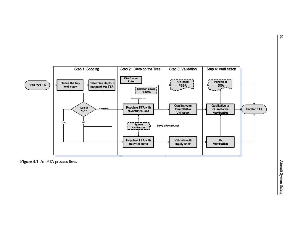
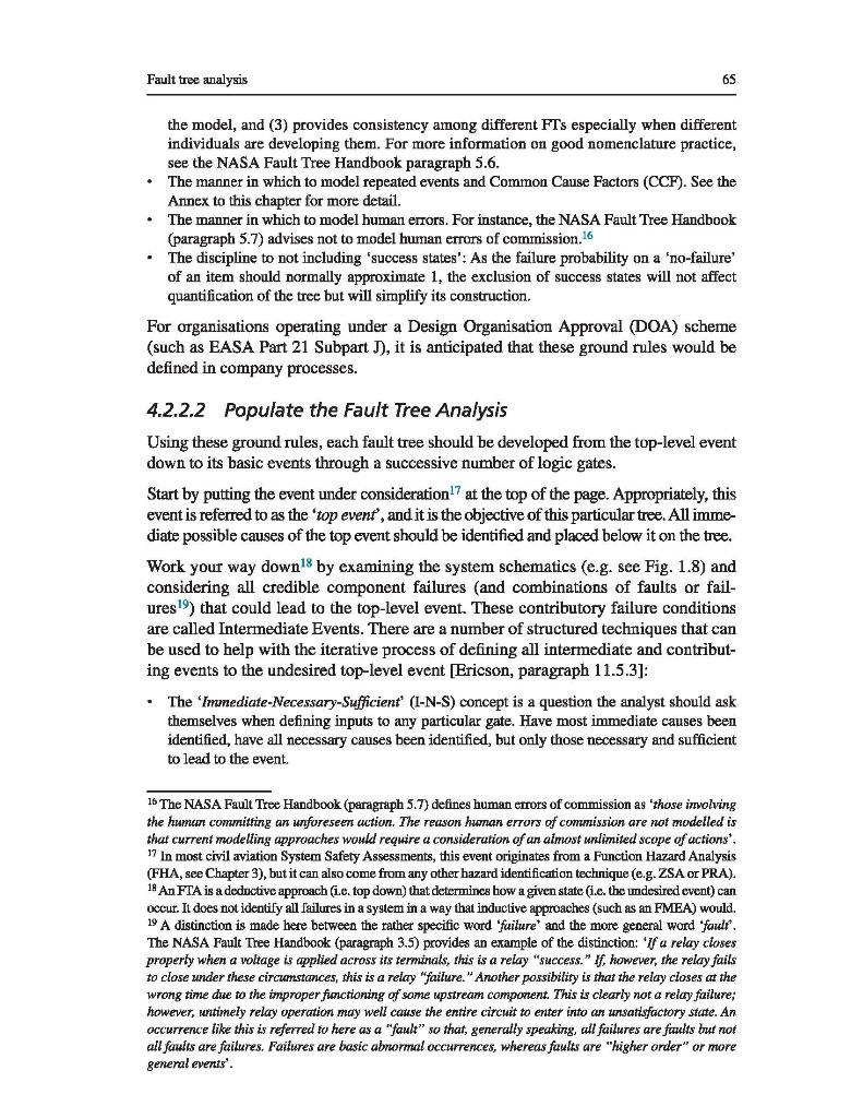
Fault tree analysis 61 4.1.3 Objectives of the Fault Tree Analysis An FTA is conducted to satisfy any of the following objectives: • Improve understanding of system characteristics by diagrammatically representing the sys- tem architecture. This then: • Assists the safety assessor in identifying the logical combination of events that must first happen for an undesirable outcome to occur. Facilitates the optimising of maintenance effort (as fault diagnostics should benefit from the logic of the FTA). • Prove the accomplishment of Functional Hazard Analysis (FHA) safety targets: . Allows for quantitative evaluation of a probability for the undesirable outcome, so eval- uating the ability of a chosen architecture to meet its safety/reliability requirements. Allocate the Development Assurance Level (DAL) to determine the rigour neces- sary when demonstrating compliance using RTCA/DO-178, RTCA/DO-254 and SAE ARP4754A. 4.1.4 Scope of the Fault Tree Analysis The FTA is initiated because of a concerned top-level event (e.g. originating from an FHA) and goes down through a succession of logic gates to basic events (i.e. an event which does not need to be broken down any further). An FTA can be conducted for both positive and negative events: • The logic tree segments leading to a Negative Event, such as an accident, defines all of the things that could go wrong to cause the negative event. Logic tree segments for negative events usually use more OR gates than AND gates, except for redundant safeguards. The logic tree segment leading to a positive event defines all of the things that must work together for the machine to operate or to complete a successful mission. Logic trees for positive events generally use more AND gates than OR gates, except for redundancy. Maintenance troubleshooting trees are a good example of logic trees for positive events. Inverting the output of a positive event converts it into a negative event. 4.2 Conducting the Fault Tree Analysis Fig. 4.1 provides a simple illustration of a typical FTA process. Note that the process is iterative, as it is repeated whenever the system architecture changes and/or when a new contributory cause is identified (e.g. via the Common Cause Analyses of Chapters 7 and 8). 4.2.1 Step 1: scope the analysis The first step for a successful FTA is to define the objective of the FTA. The resulting scope of the FTAS will depend on the exact phrasing of the top-level event as well as the scope of the controlling System Safety Assessment (e.g. see Fig. 2.5). Careful 8 See Chapter 9 for more information on the DAL approach.
Fault tree analysis 61 4.1.3 Objectives of the Fault Tree Analysis An FTA is conducted to satisfy any of the following objectives: • Improve understanding of system characteristics by diagrammatically representing the sys- tem architecture. This then: • Assists the safety assessor in identifying the logical combination of events that must first happen for an undesirable outcome to occur. Facilitates the optimising of maintenance effort (as fault diagnostics should benefit from the logic of the FTA). • Prove the accomplishment of Functional Hazard Analysis (FHA) safety targets: . Allows for quantitative evaluation of a probability for the undesirable outcome, so eval- uating the ability of a chosen architecture to meet its safety/reliability requirements. Allocate the Development Assurance Level (DAL) to determine the rigour neces- sary when demonstrating compliance using RTCA/DO-178, RTCA/DO-254 and SAE ARP4754A. 4.1.4 Scope of the Fault Tree Analysis The FTA is initiated because of a concerned top-level event (e.g. originating from an FHA) and goes down through a succession of logic gates to basic events (i.e. an event which does not need to be broken down any further). An FTA can be conducted for both positive and negative events: • The logic tree segments leading to a Negative Event, such as an accident, defines all of the things that could go wrong to cause the negative event. Logic tree segments for negative events usually use more OR gates than AND gates, except for redundant safeguards. The logic tree segment leading to a positive event defines all of the things that must work together for the machine to operate or to complete a successful mission. Logic trees for positive events generally use more AND gates than OR gates, except for redundancy. Maintenance troubleshooting trees are a good example of logic trees for positive events. Inverting the output of a positive event converts it into a negative event. 4.2 Conducting the Fault Tree Analysis Fig. 4.1 provides a simple illustration of a typical FTA process. Note that the process is iterative, as it is repeated whenever the system architecture changes and/or when a new contributory cause is identified (e.g. via the Common Cause Analyses of Chapters 7 and 8). 4.2.1 Step 1: scope the analysis The first step for a successful FTA is to define the objective of the FTA. The resulting scope of the FTAS will depend on the exact phrasing of the top-level event as well as the scope of the controlling System Safety Assessment (e.g. see Fig. 2.5). Careful 8 See Chapter 9 for more information on the DAL approach.
Step 1: Scoping Define the top level event DAL Figure 4.1 An FTA process flow. Start for FTA Type of FTA? Determine depth & scope of the FTA Reliability Step 2: Develop the Tree FTA Ground Rules Common Cause Fallures ?????? Populate FTA with relevant causes ----- System Architecture ????????? Populate FTA with relevant items Step 3: Validation Publish in PSSA ----- Qualitative or Quantitative Validation Safety criteria not met- Validate with supply chain Step 4: Verification Publish in SSA Qualitative or Quantitative Verification DAL Verification End for FTA 62 Aircraft System Safety
Fault tree analysis definition of the top event is thus necessary: if too general, the analysis becomes unmanageable while, if too specific, the analysis does not provide a sufficiently broad view of the system. If the top event is poorly defined, then the entire assessment will become unfocused. In support of a CS/FAR2x. 1309 Safety Assessment, the top event should be a functional failure description (i.e. what occurred or did not occur), not a description of the end result. Typically, the top events are defined/identified via a higher level analysis, such as the FHA, see Step 2 in Fig. 3.2. The assessor then needs to clarify what the aim of the FTA is, and it could be for either (or all) of the reasons below: A 'Reliability FTA' is aimed at assessing random failures (see Section 1.3) against which probabilistic safety targets have been set (typically generated for complex systems with fail- ure conditions with a high severity, see Fig. 3.3 for guidance in this regard). With reference to Section 2.3.1, this type of FTA is typically aimed at proving compliance to CS25.1309(b). A 'DAL FTA' is aimed at assessing systemic failures (see Section 1.3). It is always generated from an FHA so that Functional DALS (FDAL) and Item DALS (IDAL) (see Chapter 9) can be allocated to the engineering development process. When developing the DAL FTA we restrict its content to the boundaries of system architecture and the process which created it [i.e. we do not incorporate operational inputs such as crew or maintenance error or any Par- ticular Risk Analysis (PRA) events]. With reference to Section 2.3.1, FTA is typically aimed at proving compliance to CS25.1309(a)(1). A 'Human Factors FTA' is aimed at modelling all potential Human Errors (refer Table 10.1 and Table 6.1) to determine the likely human error contributions to the top event. With reference to Section 2.3.1, this type of FTA is typically aimed at proving compliance to CS25.1309(c), where flight crew warnings are used to mitigate failure conditions. Depend- ing on the top-level failure condition, some of these Human Factors FTAs might need to be incorporated (or transferred) into the Reliability and/or DAL FTAs discussed above. For instance, a Human Factors FTA might identify a condition where a warning system can be used to mitigate a Catastrophic top event. In this case, failure of the warning system must be included within the Reliability FTA for the related failure condition. The depth (or resolution) of the FTA will depend on the system level under consider- ation (refer to the example in Fig. 1.1) as well as the boundaries of the system: • Most system integrators (i.e. System Level 3 and 4 in Fig. 1.1) would not go below black box [i.e. Line Replaceable Unit (LRU)] level, expecting the component design authority (i.e. Level 2 in Fig. 1.1) to provide the relevant failure modes and substantiated probability of each of those failure modes. The NASA Fault Tree Handbook (paragraph 5.7) advises to model to the highest level for which data exist and for which there are no common hardware interfaces with other contributors.10 It is, however, important to show the supporting interfaces (such as supply of power or cooling air). These interfaces are what determine whether there are any hardwired or functional dependencies among the components [NASA Fault Tree Handbook, paragraph 4.7]. ? It is better to detail the particular failure mode than to generically state failure of a particular unit, as the way the unit fails will likely change the effect on the system. For instance, a power failure would not result in power being applied to a particular signal when not required. However, as MTBF covers the failure of any component within the unit, it can serve as a worst-case figure for probability of failure for any interested failure modes. 10 Modelling to a lower level will not only be a waste of time but will often provide erroneous probabilities or probabilities with much larger uncertainties. This is an example the fault tree maxim - 'too much detail, too much uncertainty.
64 Aircraft System Safety Component designers (i.e. System Level 2 in Fig. 1.1) may be required by the system inte- grator to develop a piece-part FTA with a top-level event for particular failure modes of a unit. The piece-part FTA would then develop through layers of logic gates until individual component failures (resistors, capacitors, etc.) are identified. This is often supported by a Failure Modes and Effects Analysis (FMEA) from which a Failure Modes and Effects Sum- mary (FMES) (see Chapter 5) can be generated for the individual next or end effects. For a subsystem (i.e. Level 3 in Fig. 1.1) FTA, where the supplier of that subsystem is not the integrator, a decision would also need to be made if the scope includes failures from events outside the system boundary (e.g. the probability of power supply failure to the LRU or the probability of maintenance error). When it comes to wiring between components, the NASA Fault Tree Handbook (paragraph 5.7.2) advises not to model wiring faults between components¹1 unless there are (1) no signifi- cantly higher contributors or (2) if the wiring can be impacted by other failures (e.g. a fire) or (3) if the objective ¹2 includes (e.g. see FAR/CS25.1709) the modelling of wiring faults. Finally, as with any other modelling technique, the boundaries of the FTA must be defined. Paragraph 3.3 of the NASA Fault Tree Handbook advises that 'If system failure is analysed as the undesired event, then defining the boundary of the analysis involves defining the boundary of the system that will be analysed. Interfaces to the system such as power sources or water supplies are typically included in an analysis and are therefore within the analysis boundary. If they are excluded from the analysis, then their states need to be defined to define the inputs to the components that are analysed." 4.2.2 Step 2: develop the fault tree 4.2.2.1 Ground rules Before the FTA is started, it is important to define the FTA ground rules (refer to Fig. 3-1 in the NASA Fault Tree Handbook). These ground rules¹3 include: The procedure and nomenclature¹4 by which events and gates are named in the FT, as this (1) is very important in creating an understandable FTA, (2) ensures that correct cut sets ¹5 and probabilities are calculated if gate or basic events occur more than once in 11 Generally, wiring faults, such as shorts to ground and shorts to power, have very low probabilities com- pared to probabilities of major components failing. 12 An example of such an objective is in CS25.1309(d), which states that 'Electrical wiring interconnection systems must be assessed in accordance with the requirements of CS 25.1709. CS25.1709 states that 'EWIS must be designed and installed so that: signed and one at the (a) Each catastrophic failure condition (1) is extremely improbable; and (2) does not result from a single failure; and (b) Each hazardous failure condition is extremely remote'. 13 The construction of fault trees is a process that has evolved gradually over a period of about 50 years. In the beginning it was thought of as an art, but it was soon realised that successful trees were best drawn in accordance with a set of basic rules. Observance of these rules helps to ensure successful fault trees so that the ocess is now less of an art and more of a science. For a lot more details on suggested ground rules, see paragraph 4.5 in the NASA Fault Tree Handbook. 14 Establish a naming (or labelling) convention for the FTA and stick to it. Avoid using words such as 'fail' as it may not be descriptive enough (e.g. 'power supply fails' versus 'power supply does not provide +5VDC"). 15 The cut sets are the combination of failure events that can cause the top event to occur. They reveal the critical and weak links in a system design.
Fault tree analysis 65 the model, and (3) provides consistency among different FTs especially when different individuals are developing them. For more information on good nomenclature practice, see the NASA Fault Tree Handbook paragraph 5.6. • The manner in which to model repeated events and Common Cause Factors (CCF). See the Annex to this chapter for more detail. The manner in which to model human errors. For instance, the NASA Fault Tree Handbook (paragraph 5.7) advises not to model human errors of commission.16 • The discipline to not including 'success states': As the failure probability on a 'no-failure' of an item should normally approximate 1, the exclusion of success states will not affect quantification of the tree but will simplify its construction. For organisations operating under a Design Organisation Approval (DOA) scheme (such as EASA Part 21 Subpart J), it is anticipated that these ground rules would be defined in company processes. 4.2.2.2 Populate the Fault Tree Analysis Using these ground rules, each fault tree should be developed from the top-level event down to its basic events through a successive number of logic gates. Start by putting the event under consideration¹7 at the top of the page. Appropriately, this event is referred to as the 'top event, and it is the objective of this particular tree. All imme- diate possible causes of the top event should be identified and placed below it on the tree. Work your way down¹8 by examining the system schematics (e.g. see Fig. 1.8) and considering all credible component failures (and combinations of faults or fail- ures¹9) that could lead to the top-level event. These contributory failure conditions are called Intermediate Events. There are a number of structured techniques that can be used to help with the iterative process of defining all intermediate and contribut- ing events to the undesired top-level event [Ericson, paragraph 11.5.3]: • The 'Immediate-Necessary-Sufficient' (I-N-S) concept is a question the analyst should ask themselves when defining inputs to any particular gate. Have most immediate causes been identified, have all necessary causes been identified, but only those necessary and sufficient to lead to the event. 15 The NASA Fault Tree Handbook (paragraph 5.7) defines human errors of commission as 'those involving the human committing an unforeseen action. The reason human errors of commission are not modelled is that current modelling approaches would require a consideration of an almost unlimited scope of actions'. 17 In most civil aviation System Safety Assessments, this event originates from a Function Hazard Analysis (FHA, see Chapter 3), but it can also come from any other hazard identification technique (e.g. ZSA or PRA). 18 An FTA is a deductive approach (L.e. top down) that determines how a given state (i.e. the undesired event) can "PE T? 19 occur. It does not identify all failures in a system in a way that inductive approaches (such as an FMEA) would. A distinction is made here between the rather specific word 'failure' and the more general word 'fault. The NASA Fault Tree Handbook (paragraph 3.5) provides an example of the distinction: 'If a relay closes property when a voltage is applied across its terminals, this is is a relay "success." If, however, the relay fails to close under these circumstances, this is a relay "failure." Another possibility is that the relay closes at the wrong time due to the improper functioning some upstream component. This is clearly not a relay failure; however, untimely relay operation may well cause the entire circuit to enter into an unsatisfactory state. An occurrence like this is referred to here as a "fault" so that, generally speaking, all failures are faults but not all faults are failures. Failures are basic abnormal occurrences, whereas faults are "higher order" or more general events".
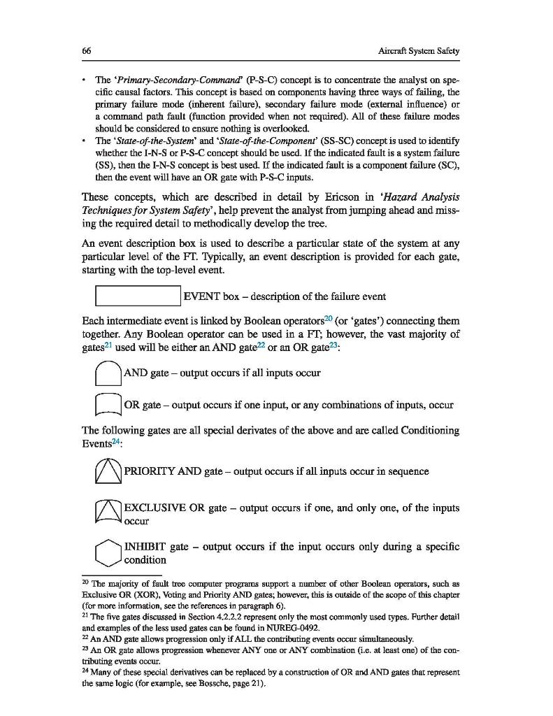
66 Aircraft System Safety The 'Primary-Secondary-Command (P-S-C) concept is to concentrate the analyst on spe- cific causal factors. This concept is based on components having three ways of failing, the primary failure mode (inherent failure), secondary failure mode (external influence) or a command path fault (function provided when not required). All of these failure modes should be considered to ensure nothing is overlooked. The 'State-of-the-System' and 'State-of-the-Component' (SS-SC) concept is used to identify whether the I-N-S or P-S-C concept should be used. If the indicated fault is a system failure (SS), then the I-N-S concept is best used. If the indicated fault is a component failure (SC), then the event will have an OR gate with P-S-C inputs. These concepts, which are described in detail by Ericson in 'Hazard Analysis Techniques for System Safety', help prevent the analyst from jumping ahead and miss- ing the required detail to methodically develop the tree. An event description box is used to describe a particular state of the system at any particular level of the FT. Typically, an event description is provided for each gate, starting with the top-level event. EVENT box - description of the failure event Each intermediate event is linked by Boolean operators20 (or 'gates') connecting them together. Any Boolean operator can be used in a FT; however, the vast majority of gates2¹ used will be either an AND gate22 or an OR gate ²3. AND gate - output occurs if all inputs occur OR gate - output occurs if one input, or any combinations of inputs, occur The following gates are all special derivates of the above and are called Conditioning Events24: PRIORITY AND gate- output occurs if all inputs occur in sequence EXCLUSIVE OR gate - output occurs if one, and only one, of the inputs occur INHIBIT gate output occurs if the input occurs only during a specific condition 20 The majority of fault tree computer programs support a number of other Boolean operators, such as Exclusive OR (XOR), Voting and Priority AND gates; however, this is outside of the scope of this chapter (for more information, see the references in paragraph 6). 21 The five gates discussed in Section 4.2.2.2 represent only the most commonly used types. Further detail and examples of the less used gates can be found in NUREG-0492. 22 An AND gate allows progression only if ALL the contributing events occur simultaneously. 23 An t OR progression whenever ANY one or ANY combination (i.c. at least one) of the con- tributing events occur. 24 Many of these special derivatives can be replaced by a construction of OR and AND gates that represent the same logic (for example, see Bossche, page 21).