(Solved): Q. 2 The circuit shown in Fig.Q. 2 represents that of a strain gauge bridge driven by an excitatio ...
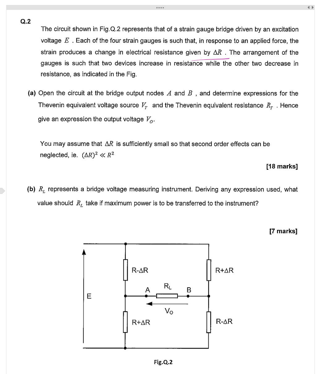
Q. 2 The circuit shown in Fig.Q. 2 represents that of a strain gauge bridge driven by an excitation voltage
E. Each of the four strain gauges is such that, in response to an applied force, the strain produces a change in electrical resistance given by
\Delta R. The arrangement of the gauges is such that two devices increase in resistance while the other two decrease in resistance, as indicated in the Fig. (a) Open the circuit at the bridge output nodes
Aand
B, and determine expressions for the Thevenin equivalent voltage source
V_(T)and the Thevenin equivalent resistance
R_(T). Hence give an expression the output voltage
V_(o). You may assume that
\Delta Ris sufficiently small so that second order effects can be neglected, ie.
(\Delta R)^(2)≪R^(2)[18 marks] (b)
R_(L)represents a bridge voltage measuring instrument. Deriving any expression used, what value should
R_(L)take if maximum power is to be transferred to the instrument?