Home /
Expert Answers /
Electrical Engineering /
q1-the-single-line-diagram-of-an-unloaded-power-system-is-shown-below-the-lengths-of-the-transmis-pa370
(Solved): Q1. The single-line diagram of an unloaded power system is shown below. The lengths of the transmis ...
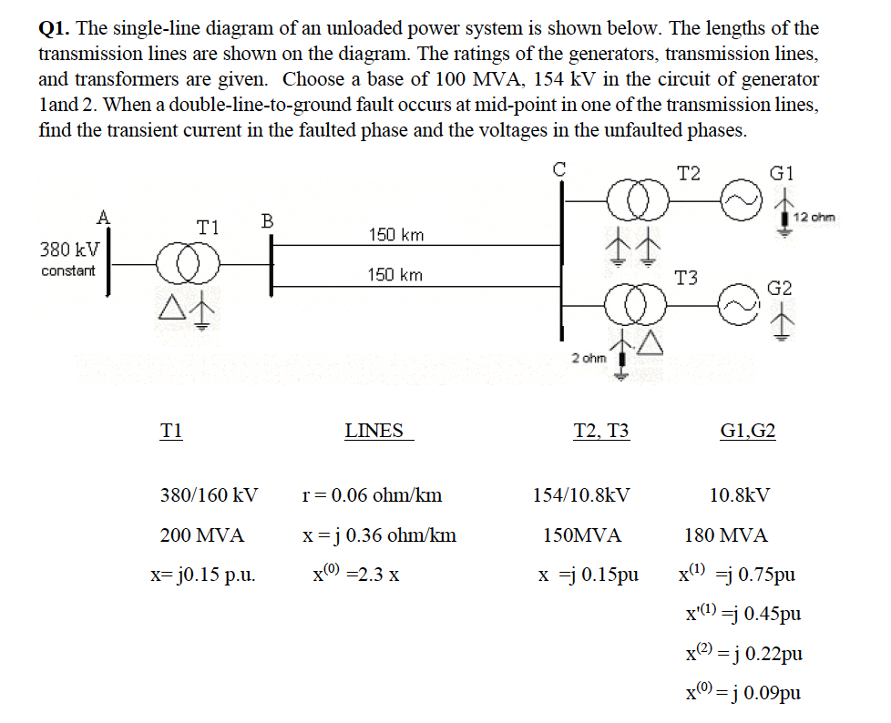
Q1. The single-line diagram of an unloaded power system is shown below. The lengths of the transmission lines are shown on the diagram. The ratings of the generators, transmission lines, and transformers are given. Choose a base of 100 MVA, in the circuit of generator land 2. When a double-line-to-ground fault occurs at mid-point in one of the transmission lines, find the transient current in the faulted phase and the voltages in the unfaulted phases.
Expert Answer
To analyze the transient current and voltages during a double-line-to-ground fault, we need to determine the fault current and calculate the voltages in the unfaulted phases.Let's start by converting the given ratings and impedances to the base of 100 MVA and 154 kV.Given data:Base power (Sbase) = 100 MVABase voltage (Vbase) = 154 kVGenerator G1:Rated power (SG1) = 200 MVARated voltage (VG1) = 380 kVGenerator G2:Rated power (SG2) = 200 MVARated voltage (VG2) = 380 kVTransformer T1:Rated power (ST1) = 150 MVAPrimary voltage (VT1_prim) = 380 kVSecondary voltage (VT1_sec) = 160 kVTransformer T2, T3:Rated power (ST2) = 180 MVAPrimary voltage (VT2_prim) = 154 kVSecondary voltage (VT2_sec) = 10.8 kVTransmission Line 1:Length (L1) = r1 = 150 kmImpedance (Z1) = r1 + jx1 = 0.06 ohm/km + j0.36 ohm/kmTransmission Line 2:Length (L2) = r2 = 100 kmImpedance (Z2) = r2 + jx2 = 0.06 ohm/km + j0.15 ohm/kmTransmission Line 3:Length (L3) = r3 = 100 kmImpedance (Z3) = r3 + jx3 = 0.06 ohm/km + j0.15 ohm/km