Home /
Expert Answers /
Mechanical Engineering /
q3-in-a-swiveling-joint-mechanism-as-shown-in-figure-q3-the-driving-crank-oa-is-rotat-pa166
(Solved): ; = Q3/ In a swiveling joint mechanism, as shown in Figure(Q3), the driving crank OA is rotat ...
ᎠᏴ ; = Q3/ In a swiveling joint mechanism, as shown in Figure(Q3), the driving crank OA is rotating clockwise at 100 r.p.m. The lengths of various links are : OA = 50 mm; AB = 350 mm; AD DE = EF = 250 mm and CB = 125 mm. The horizontal distance between the fixed points O and C is 300 mm and the vertical distance between F and C is 250 mm. For the given configuration, determine: 1. Velocity of the slider block F, 2. Angular velocity of the link DE, 3. Velocity of sliding of the link DE in the swivel block, and 4. Acceleration of sliding of the link DE in the trunnion. A 45° O TTATT Swivel block D 180 300 E S 150 B All dimensions in mm. Figure (Q3) 250 =
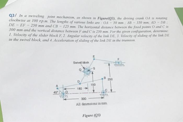
Q3/ In a swiveling joint mechanism, as shown in Figure(Q3), the driving crank is rotating clockwise at 100 r.p.m. The lengths of various links are: : and . The horizontal distance between the fixed points and is and the vertical distance between and is . For the given configuration, determine: 1. Velocity of the slider block . Angular velocity of the link . Velocity of sliding of the link in the swivel block, and 4. Acceleration of sliding of the link DE in the trunnion. Figure (Q3)