(Solved): Simulation: Implementation in Logisim: Build the Moore and Mealy machine using D-FF on Logisim. Ti ...
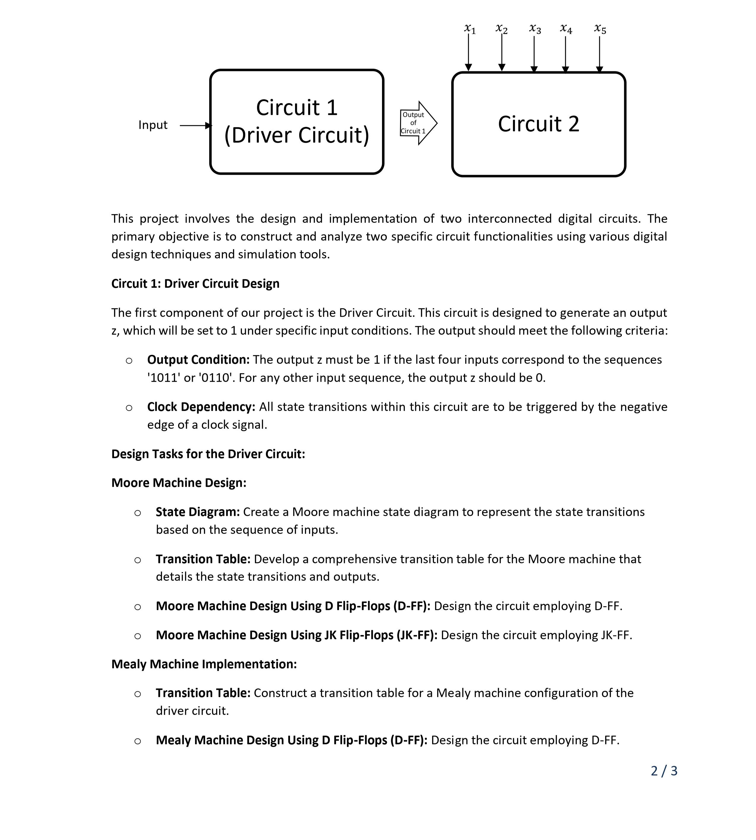
Simulation: Implementation in Logisim: Build the Moore and Mealy machine using D-FF on Logisim. Timing Diagram: Produce a timing diagram depicting the circuit's behavior over 30 clock cycles. Circuit 2: Dependent Circuit Activation The second circuit is activated based on the output from the Driver Circuit. It should only be operational when the Driver Circuit's output
zis 1 . The functionality of this circuit is based on a Boolean function given as follows:
f(x_(1),x_(2),x_(3),x_(4),x_(5))=\sum (0,3,7,14,15,16,19,23,30,31)Design Tasks for the Second Circuit: Boolean Minimization: Utilize Boolean algebra techniques to simplify the given function. Circuit Design: Draw circuit post-minimization. Integrated Circuit Layout: Combined Schematic: Draw a comprehensive schematic that integrates both the Driver Circuit and the second circuit. Simulation: Implementation in Logisim: Construct and verify the functionality of the combined circuits in Logisim. Timing Diagram: Generate a timing diagram displaying the output behavior of the first and second circuit over 30 clock cycles. This project involves the design and implementation of two interconnected digital circuits. The primary objective is to construct and analyze two specific circuit functionalities using various digital design techniques and simulation tools. Circuit 1: Driver Circuit Design The first component of our project is the Driver Circuit. This circuit is designed to generate an output
z, which will be set to 1 under specific input conditions. The output should meet the following criteria: Output Condition: The output z must be 1 if the last four inputs correspond to the sequences '1011' or '0110'. For any other input sequence, the output z should be 0. Clock Dependency: All state transitions within this circuit are to be triggered by the negative edge of a clock signal. Design Tasks for the Driver Circuit: Moore Machine Design: State Diagram: Create a Moore machine state diagram to represent the state transitions based on the sequence of inputs. Transition Table: Develop a comprehensive transition table for the Moore machine that details the state transitions and outputs. Moore Machine Design Using D Flip-Flops (D-FF): Design the circuit employing D-FF. ○ Moore Machine Design Using JK Flip-Flops (JK-FF): Design the circuit employing JK-FF. Mealy Machine Implementation: Transition Table: Construct a transition table for a Mealy machine configuration of the driver circuit. Mealy Machine Design Using D Flip-Flops (D-FF): Design the circuit employing D-FF.