Home /
Expert Answers /
Advanced Physics /
simulink-open-loop-system-time-constants-and-end-values-i-don-t-know-how-to-solve-assignment-2b-a-pa348
(Solved): Simulink: open loop system, Time constants and end values I don`t know how to solve assignment 2b, a ...
Simulink: open loop system, Time constants and end values
I don`t know how to solve assignment 2b, any ideas?
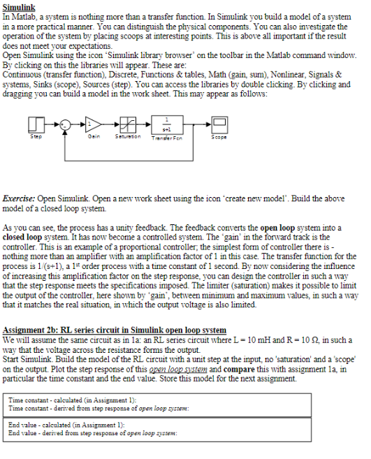
Simulink In Matlab, a system is nothing more than a transfer function. In Simulink you build a model of a system in a more practical manner. You can distinguish the physical components. You can also investigate the operation of the system by placing scoops at interesting points. This is above all important if the result does not meet your expectations. Open Simulink using the icon "Simulink library browser on the toolbar in the Matlab command window. By clicking on this the libraries will appear. These are: Continuous (transfer function), Discrete, Functions & tables, Math (gain, sum), Nonlinear, Signals & systems, Sinks (scope), Sources (step). You can access the libraries by double clicking. By clicking and dragging you can build a model in the work sheet. This may appear as follows: s+1 Step Gain Saturation Transfer Fen Scope Exercise: Open Simulink. Open a new work sheet using the icon 'create new model. Build the above model of a closed loop system. As you can see, the process has a unity feedback. The feedback converts the open loop system into a closed loop system. It has now become a controlled system. The gain' in the forward track is the controller. This is an example of a proportional controller; the simplest form of controller there is - nothing more than an amplifier with an amplification factor of 1 in this case. The transfer function for the process is 1/(s+1), a 1st order process with a time constant of 1 second. By now considering the influence of increasing this amplification factor on the step response, you can design the controller in such a way that the step response meets the specifications imposed. The limiter (saturation) makes it possible to limit the output of the controller, here shown by gain', between minimum and maximum values, in such a way that it matches the real situation, in which the output voltage is also limited. Assignment 2b: RL series circuit in Simulink open loop system We will assume the same circuit as in 1a: an RL series circuit where L = 10 mH and R = 10 92, in such a way that the voltage across the resistance forms the output. Start Simulink. Build the model of the RL circuit with a unit step at the input, no 'saturation' and a 'scope' on the output. Plot the step response of this open loop system and compare this with assignment la, in particular the time constant and the end value. Store this model for the next assignment. Time constant - calculated (in Assignment 1): Time constant-derived from step response of open loop system: End value-calculated (in Assignment 1): End value - derived from step response of open loop system: