(Solved): The basic ILS system consists of two horizontal dipole antennas mounted on a tower. Antenna \#1 is ...
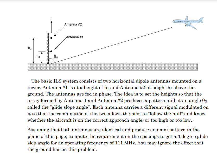
The basic ILS system consists of two horizontal dipole antennas mounted on a tower. Antenna \#1 is at a height of \( h_{1} \) and Antenna \#2 at height \( h_{2} \) above the ground. The antennas are fed in phase. The idea is to set the heights so that the array formed by Antenna 1 and Antenna \#2 produces a pattern null at an angle \( \theta_{G} \) called the "glide slope angle". Each antenna carries a different signal modulated on it so that the combination of the two allows the pilot to "follow the null" and know whether the aircraft is on the correct approach angle, or too high or too low. Assuming that both antennas are identical and produce an omni pattern in the plane of this page, compute the requirement on the spacings to get a 3 degree glide slop angle for an operating frequency of 111 MHz . You may ignore the effect that the ground has on this problem.