Home /
Expert Answers /
Mechanical Engineering /
the-drawing-scale-is-1-cm-1-cm-for-mechanism-and-1-cm-100-cm-sec-2-for-acceleration-diagram-pa126
(Solved): The drawing scale is [1 cm: 1 cm] for mechanism and [1 cm: 100 cm.sec-2] for acceleration diagram. ...
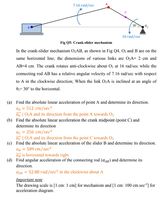
The drawing scale is [1 cm: 1 cm] for mechanism and [1 cm: 100 cm.sec-2] for acceleration diagram.
7.16 rad/sec 30° B 16 rad/sec Fig 25: Crank-slider mechanism In the crank-slider mechanism O2AB, as shown in Fig 04, O2 and B are on the same horizontal line; the dimensions of various links are 02A= 2 cm and AB=4 cm. The crank rotates anti-clockwise about 02 at 16 rad/sec while the connecting rod AB has a relative angular velocity of 7.16 rad/sec with respect to A in the clockwise direction; When the link 02A is inclined at an angle of 02= 30° to the horizontal (a) Find the absolute linear acceleration of point A and determine its direction. QA = 512 cm/sec? ?i || 02A and its direction from the point A towards 02. (b) Find the absolute linear acceleration the crank midpoint (point C) and determine its direction ac = 256 cm/sec2 ac || O2A and its direction from the point C towards 02. (c) Find the absolute linear acceleration of the slider B and determine its direction. Qp = 589 cm/sec2 ag is horizontal towards right (d) Find angular acceleration of the connecting rod (CAB) and determine its direction. QAB = 52.88 rad/sec2 in the clockwise about A Important note The drawing scale is [1 cm: 1 cm) for mechanism and [1 cm: 100 cm.sec-2] for acceleration diagram