Home /
Expert Answers /
Electrical Engineering /
the-following-figure-shows-a-half-adder-subtractor-which-accepts-in-addition-to-inputs-a-b-and-ou-pa623
(Solved): The following figure shows a half-adder/subtractor, which accepts, in addition to inputs A, B and ou ...
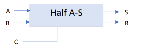
The following figure shows a half-adder/subtractor, which accepts, in addition to inputs A, B and outputs S, R, a control input C indicating the type of operation to execute. The circuit therefore performs an addition on A and B when command C is 0 and a subtraction on A and B when command C is 1. Determine the logic equations and draw the logic diagram for this circuit. Based on the half-adder/subtractor from the previous question, design a complete 1-bit adder/subtractor with an input carry (i.e., Full adder/subtractor with control input). Based on the full-adder/subtractor from the previous question, give the logic diagram of a 4-bit adder/subtractor.