(Solved): To determine the angle of twist on a composite rod given the geometry and externally applied torques ...
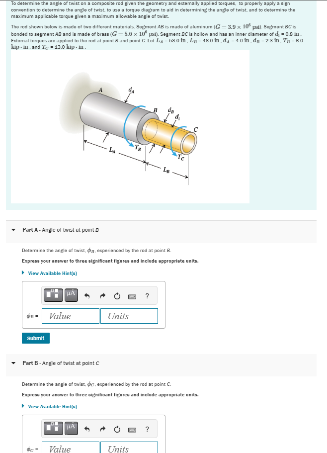
To determine the angle of twist on a composite rod given the geometry and externally applied torques, to properly apply a sign convention to determine the angle of twist, to use a torque diagram to aid in determining the angle of twist, and to determine the maximum applicable torque given a maximum allowable angle of twist. The rod shown below is made of two different materials. Segment
ABis made of aluminum (
G=3.9\times 10^(6)psi). Segment
BCis bonded to segment
ABand is made of brass (
G=5.6\times 10^(6)psi). Segment
BCis hollow and has an inner diameter of
d_(1)=0.8in. External torques are applied to the rod at point
Band point
C. Let
L_(A)=58.0in,L_(B)=46.0in,d_(A)=4.0in,d_(B)=2.3in,T_(B)=6.0kip - in , and
T_(C)=13.0kip- in . Part A - Angle of twist at point
BDetermine the angle of twist,
\phi _(B), experienced by the rod at point
B. Express your answer to three significant figures and include appropriate units. View Available Hint(s)
\phi _(B)=darr,◻Part B - Angle of twist at point C Determine the angle of twist,
\phi _(C), experienced by the rod at point
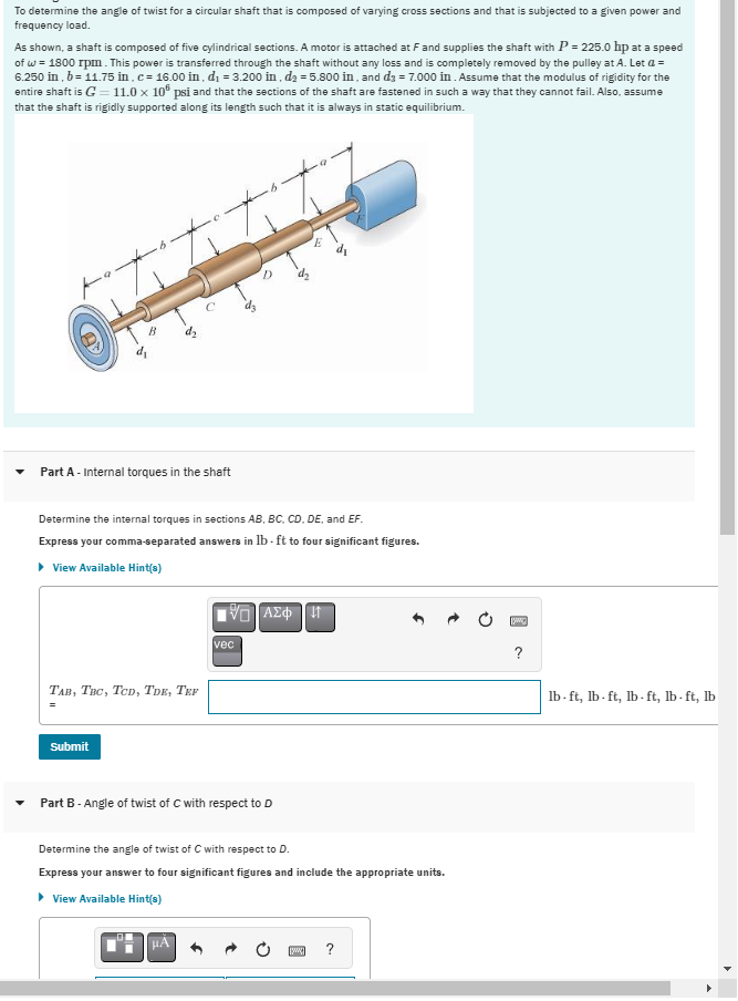
C. Express your answer to three significant figures and include appropriate units. View Available Hint(s) To determine the angle of twist for a circular shaft that is composed of varying cross sections and that is subjected to a given power and frequency load. As shown, a shaft is composed of five cylindrical sections. A motor is attached at
Fand supplies the shaft with
P=225.0hp at a speed of
\omega =1800rpm. This power is transferred through the shaft without any loss and is completely removed by the pulley at
A. Let
a=
6.250in,b=11.75in,c=16.00in,d_(1)=3.200in,d_(2)=5.800in, and
d_(3)=7.000in. Assume that the modulus of rigidity for the entire shaft is
G=11.0\times 10^(6)psi and that the sections of the shaft are fastened in such a way that they cannot fail. Also, assume that the shaft is rigidly supported along its length such that it is always in static equilibrium. Part A - Internal torques in the shaft Determine the internal torques in sections
AB,BC,CD,DE, and
EF. Express your comma-separated answers in
lb*ftto four significant figures. View Available Hint(s) Part B - Angle of twist of
Cwith respect to
DDetermine the angle of twist of
Cwith respect to
D. Express your answer to four significant figures and include the appropriate units. View Available Hint(s) Express the shear function in terms of
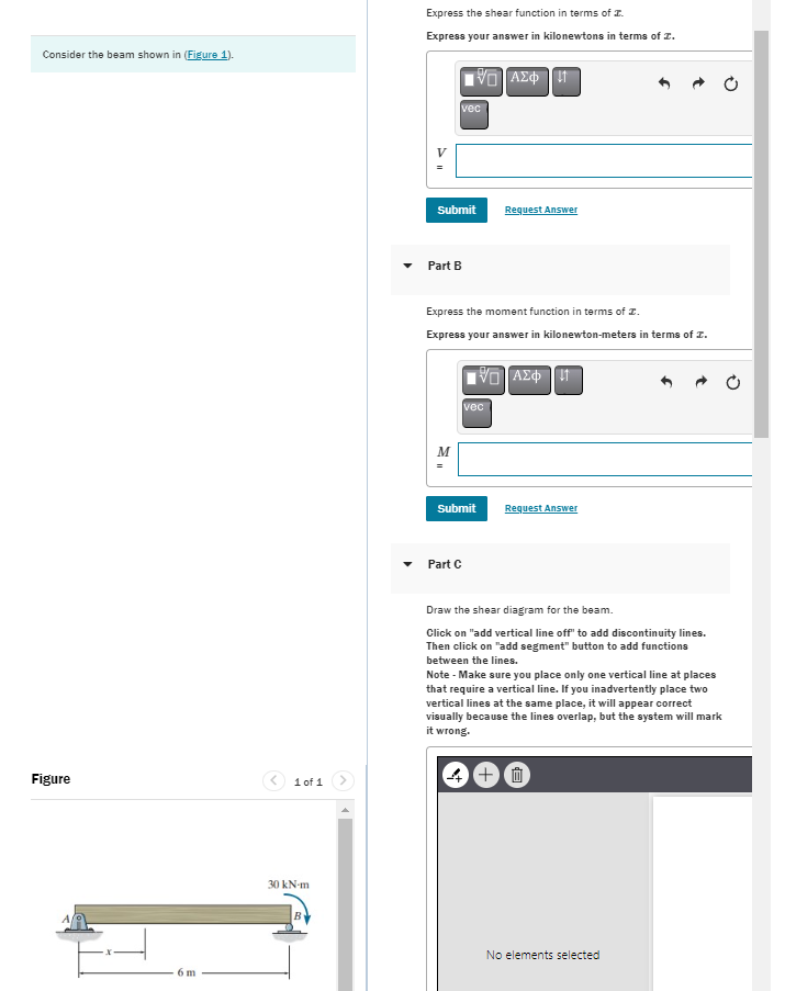
x. Consider the beam shown in (Figure 1). Express your answer in kilonewtons in terms of
x.
V
=Request Answer Part B Express the moment function in terms of
x. Express your answer in kilonewton-meters in terms of
x. Figure Part C Request Answer Draw the shear diagram for the beam. Click on "add vertical line off" to add discontinuity lines. Then click on "add segment" button to add functions between the lines. Note - Make sure you place only one vertical line at places that require a vertical line. If you inadvertently place two vertical lines at the same place, it will appear correct visually because the lines overlap, but the system will mark it wrong. (4) + 品 No elements selected


