(Solved): Traffic Light Controller FSM Specification: Main States: Green Light (G): Pedestrian light is off, ...
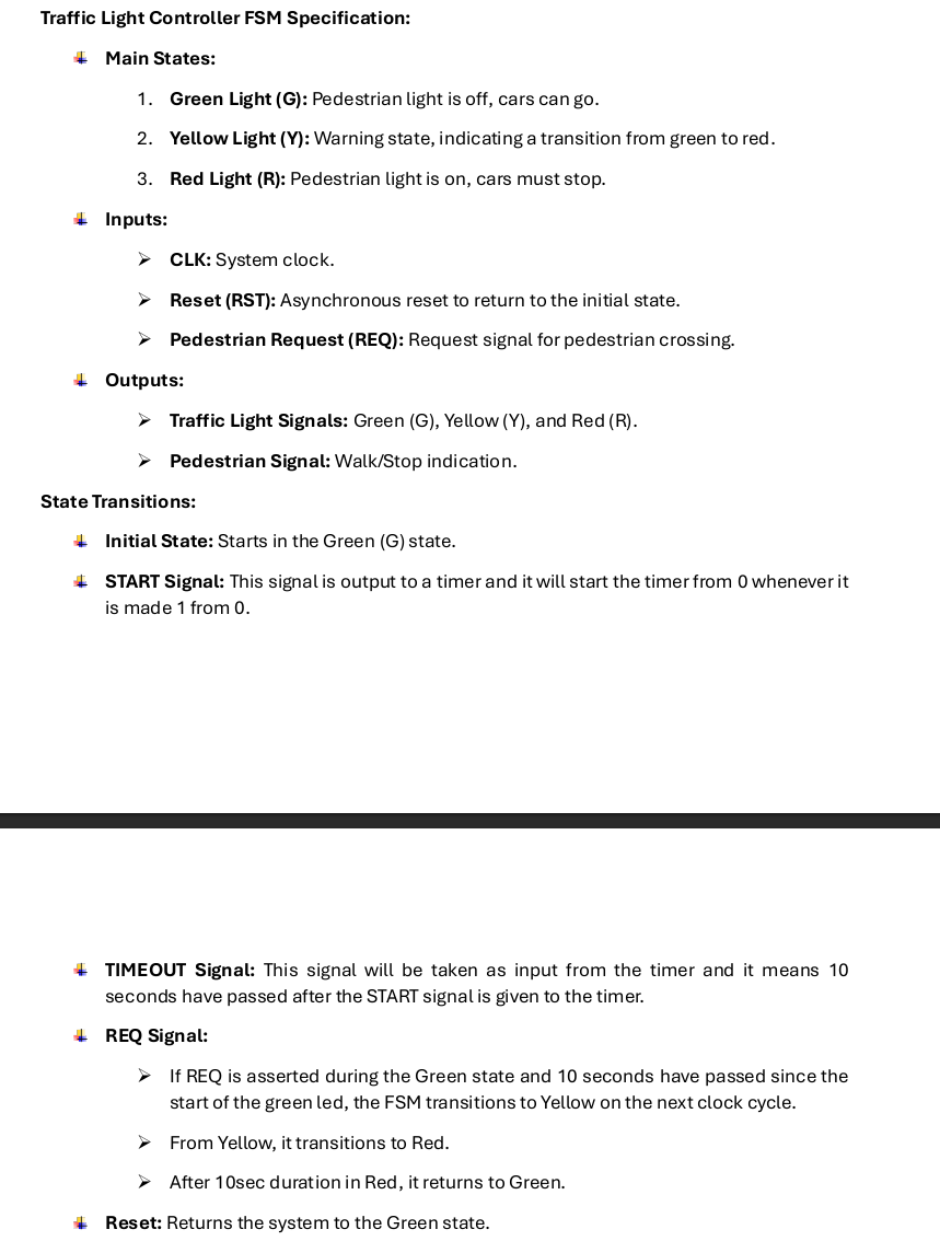
Traffic Light Controller FSM Specification: Main States: Green Light (G): Pedestrian light is off, cars can go. Yellow Light (Y): Warning state, indicating a transition from green to red. Red Light (R): Pedestrian light is on, cars must stop. Inputs: CLK: System clock. Reset (RST): Asynchronous reset to return to the initial state. Pedestrian Request (REQ): Request signal for pedestrian crossing. Outputs: Traffic Light Signals: Green (G), Yellow (Y), and Red (R). Pedestrian Signal: Walk/Stop indication. State Transitions: Initial State: Starts in the Green (G) state. START Signal: This signal is output to a timer and it will start the timer from 0 whenever it is made 1 from 0 . 4 TIMEOUT Signal: This signal will be taken as input from the timer and it means 10 seconds have passed after the START signal is given to the timer. REQ Signal: If REQ is asserted during the Green state and 10 seconds have passed since the start of the green led, the FSM transitions to Yellow on the next clock cycle. From Yellow, it transitions to Red. After 10sec duration in Red, it returns to Green. Reset: Returns the system to the Green state. 1. State Diagram and Truth Table 2. Schematic Design: Implement the FSM using D flip-flops (DFFs) for state memory and combinational logic gates for next-state logic. Use a clocked synchronous design. Use Logisim for that purpose. Your design should execute in Logisim.
