Home /
Expert Answers /
Mechanical Engineering /
volumetric-flow-rate-q-25-m-3-m-in-working-fluid-water-at-stp-impeller-i-omega-i-3-00-pa708
(Solved): Volumetric Flow Rate, Q=25(m^(3))/(m)in; Working Fluid: Water at STP Impeller #I: \omega _(I)=3,00 ...
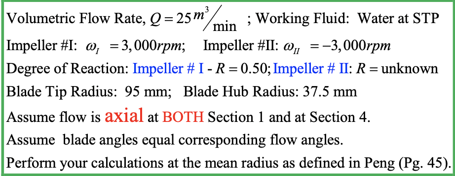
Volumetric Flow Rate,
Q=25(m^(3))/(m)in; Working Fluid: Water at STP Impeller #I:
\omega _(I)=3,000rpm;,Impeller #II:
\omega _(II)=-3,000rpmDegree of Reaction: Impeller # I -
R=0.50; Impeller # II:
R=unknown Blade Tip Radius:
95mm;Blade Hub Radius:
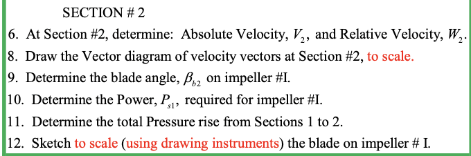
37.5mmAssume flow is axial at BOTH Section 1 and at Section 4. Assume blade angles equal corresponding flow angles. Perform your calculations at the mean radius as defined in Peng (Pg. 45). SECTION # 2 At Section #2, determine: Absolute Velocity,
V_(2), and Relative Velocity,
W_(2). Draw the Vector diagram of velocity vectors at Section #2, to scale. Determine the blade angle,
\beta _(b2)on impeller #I. Determine the Power,
P_(s1), required for impeller #I. Determine the total Pressure rise from Sections 1 to 2. Sketch to scale (using drawing instruments) the blade on impeller # I.