Home /
Expert Answers /
Electrical Engineering /
work-both-parts-with-a-detailed-solution-a-low-pass-filter-is-shown-in-fig-q2d-connected-to-5-pa210
(Solved): work both parts with a detailed solution. A low-pass filter is shown in Fig Q2d, connected to \( 5 ...
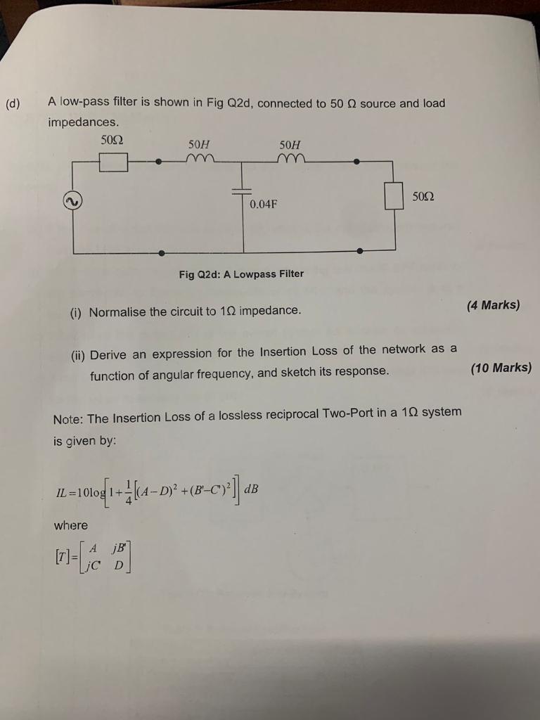
work both parts with a detailed solution.
A low-pass filter is shown in Fig Q2d, connected to \( 50 \Omega \) source and load impedances. Fig Q2d: A Lowpass Filter (i) Normalise the circuit to \( 1 \Omega \) impedance. (4 Marks) (ii) Derive an expression for the Insertion Loss of the network as a function of angular frequency, and sketch its response. (10 Marks) Note: The Insertion Loss of a lossless reciprocal Two-Port in a \( 1 \Omega \) system is given by: \[ I L=10 \log \left[1+\frac{1}{4}\left[(A-D)^{2}+\left(B^{\prime}-C^{\prime}\right)^{2}\right]\right] d B \] where \[ [T]=\left[\begin{array}{cc} A & j B^{\prime} \\ j C & D \end{array}\right] \]