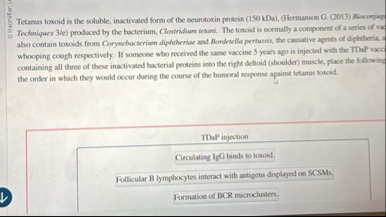
Problem #3: Relay Logic Circuit Design So now you are ready for the big time, designing a circuit to run a mechanical system. The folks in shipping are complaining that the truck dock fills up with water after a heavy rain, especially on weekends when no one is there. So the Plant Engineer wants you to go out and design a sump pump to get the water out. This is way too small a job to justify the cost of a PLC so you'll just have to grab some parts out of the back room and wire it up after you complete a schematic that meets the requirements. The job calls for a motor driven pump (there is a motor starter so you will have a coil & seal-in contact in the control circuit) that can be operated manually (Start/stop) when personnel are on site and need to pump out water, OR automatically using level sensors (such as on the weekends). The Mode of operation is set by a Hand-Off-Auto (H-O-A) switch Off-motor doesn't run (duh!); Hand - pump motor is started manually by the NO PB (aka START) and seals in to run until stopped by the NC PB (aka STOP); Auto - The pump motor operates using two float or level switches, FS1 indicates a low level of water & de-activates the pump, FS2 indicates a high level of water in the sump & activates the pump & seals it in. As an additional precaution there is a third sensor. FS3 is an alarm which indicates the sump is about to overflow (pump is off or can't keep up), it triggers an alarm horn to alert dock personnel or a security guard on the weekend, that there is a problem. There are four indicator pilot lights which visually inform dock personal of the pump status (Hand mode, Auto mode, Off), and if the pump motor is currently running or not.
Assignment: What I want you to do is design a relay ladder logic (NOT a PAC program we will get to that next time) control circuit to operate the sump pump in the dock as speasfied. You can draw on graph paper if clearly done, there are software programs that do ladder logic drawings. I want you to follow the rules as were given in the class materials (you don't have to put in wire numbers), but identify everything properly and follow the rules. Especially remember that all ladder logic load devices on the same rung (circuit) are wired as CURRENT dividers not voltage dividers (ie. in parallel, not in series). If you put a 24 V coil and a 24 V pilot light in series each gets 12 V and neither of them works because they are wired as voltage dividers.